[How-To] Use AWX and Ansible for Automation & SFC in a multi-tenant Edge & DC environment
Ansible is a powerful automation tool, widely used by administrators for the automation of configuration and management of servers.
It started being adopted by network engineers as a tool for automation of configuration and management of networking devices (bare metal or virtual). Steps of the specific automated process are implemented as tasks, defined in YAML format. Tasks can be grouped into roles with other tasks and are executed as so-called plays, defined in another YAML file called playbook.
Playbooks also associate definitions of variables and list of hosts, where the roles and tasks will be performed. All of the mentioned (tasks, roles, playbooks, variables, hosts) can be specified as YAML files with a well-defined directory structure.
This makes Ansible suitable to be used as a base of Infrastructure as Code (IaC) approach to configuration management and orchestration in the telco industry, data centers (orchestration of virtualization and networking) & many more.
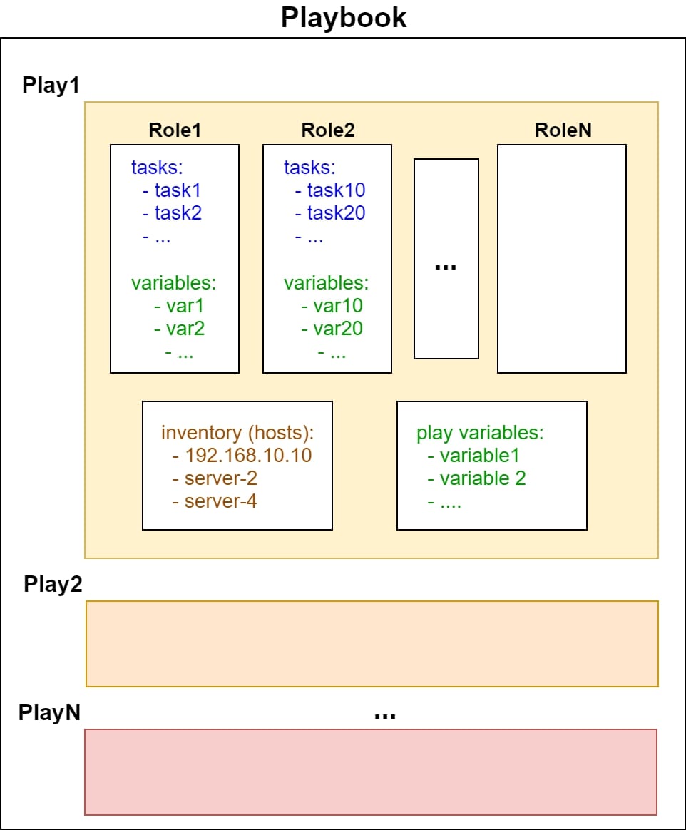
Figure A: An Ansible Playbook example structure
Ansible playbook structure
AWX provides UI and REST API on top of Ansible and also adds the management of inventories (lists of hosts and groups of hosts), credentials (SSH & more) integration with CVS (Code Versioning Systems, e.g.: Git).
In AWX, you can define job templates, which associates playbooks with repositories, credentials, configuration, etc. and you can execute them. The job templates can be used to build graphs, defining the order of execution of multiple job templates (sequentially or in parallel). Such graphs are called workflows and they can use job templates & other workflows as graph nodes.
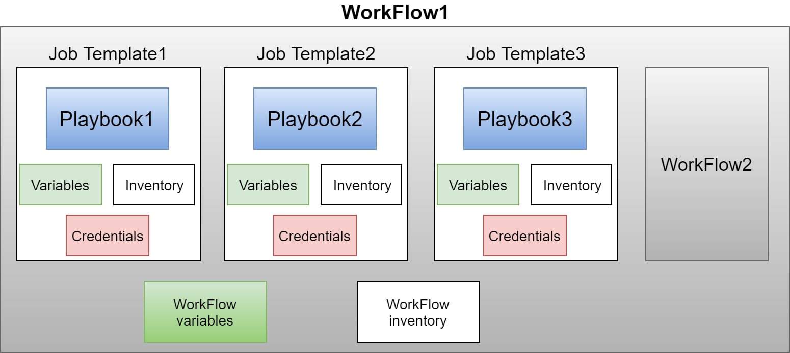
Figure B: AWX WorkFlow and Job Templates
AWX WorkFlow and Job Templates
In our previous blogs, we have demonstrated the usage of SDN controller based on lighty.io as a controller of OVSDB capable devices and OpenFlow switches.
In this article, we’re going to describe some example Ansible playbooks and Ansible modules, using an SDN controller based on lighty.io. We will also be orchestrating Open vSwitch instances as a networking infrastructure of core data centers and edge data centers. This way, we are able to build solutions, utilizing Service Functions (SFs) and Service Function Chaining (SFC), which are dedicated to a specific tenant or particular service.
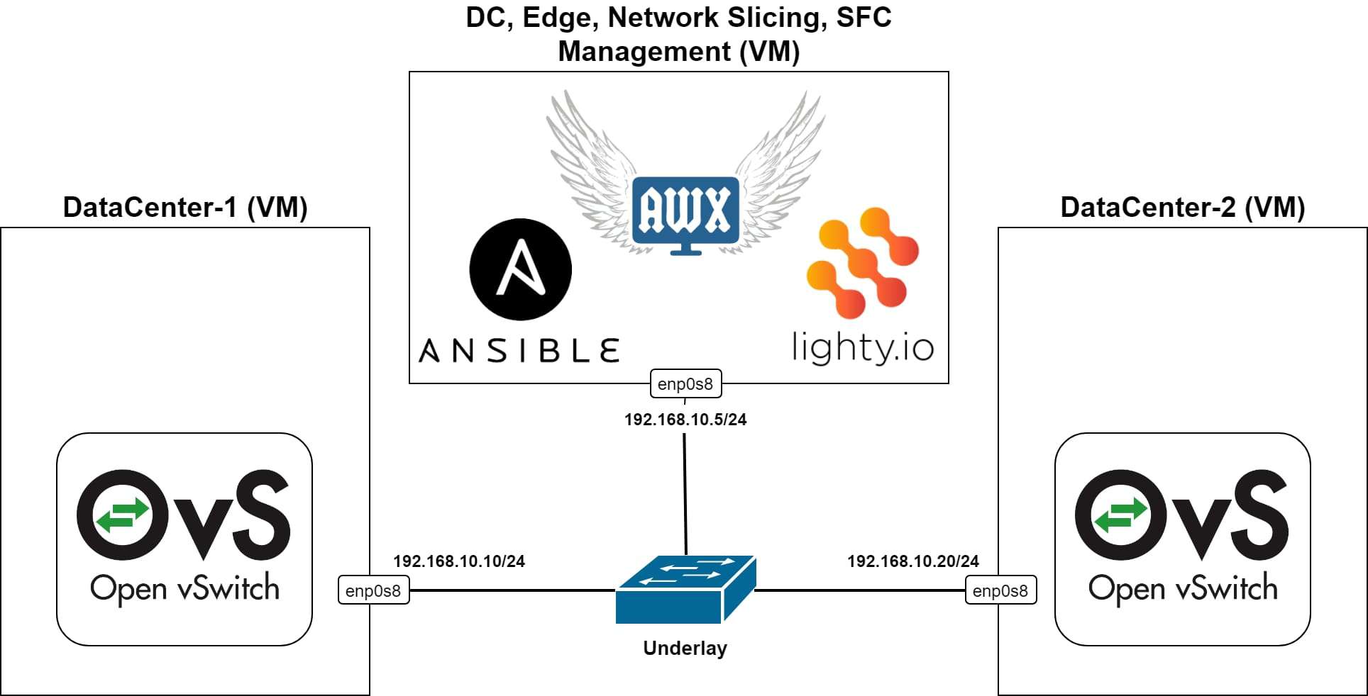
Figure 1: Data Center Simulation Setup
Data Center Simulation Setup
In the above Figure 1, we can see a topology of the testing setup, where 3 virtual machines are running in a Virtual Box and connected into an L2 switch, representing the underlay network.
Each VM has an IP address, configured from the same subnet. The two VMs simulate data centers or servers respectively. In each DC VM, there is an Open vSwitch installed and running without any configuration (using the default configuration, which will be overridden by our SDN controller), together with ovs-vsctl and ovs-ofctl utilities.
In the management VM, Ansible and AWX are installed & running. Also, an SDN controller based on lighty.io. using OVSDB and OpenFlow Southbound plugins and a RESTCONF northbound plugin is in the same VM.
This way, it is possible to use the SDN controller to manage and configure Open vSwitch instances over the HTTP REST API – according to RESTCONF specification and YANG models of OVSDB and OpenFlow plugins. See the implementation of Ansible roles and Ansible module for more details regarding specific RESTCONF requests usage.
In addition to the RESTCONF requests, Ansible uses also CLI commands over SSH to create namespaces, veth links and to connect them with a bridge instance created in respective Open vSwitch instance. OpeFlow flows are used as for configuration of rules forwarding packets from one port of virtual bride to another (and vice versa). All flow configurations are being sent as RESTCONF requests to the SDN controller which forwards them to the specific bridge of specific Open vSwitch instance.
Starting our Datacenters
We will also use a simple testing command for each DC VM. The command sends 3 ICMP echo requests from the tenant’s namespace, to the other tenant’s namespace in another DC VM. The requests are being sent in an infinite loop (using the watch command). Therefore, at first, they will show that the namespaces don’t exist (because they really don’t, according to Figure 1).
But after the successful provisioning and configuration of the desired virtual infrastructure, they should show that the ping command was successful, as we will demonstrate later.
Figure 2 and Figure 3 show an example of the output of the testing commands.
DataCenter-1:
watch sudo ip netns exec t1-s1 ping -c 3 10.10.1.2

Figure 2 for DataCenter-1
DataCenter-2:
watch sudo ip netns exec t1-s2 ping -c 3 10.10.1.1
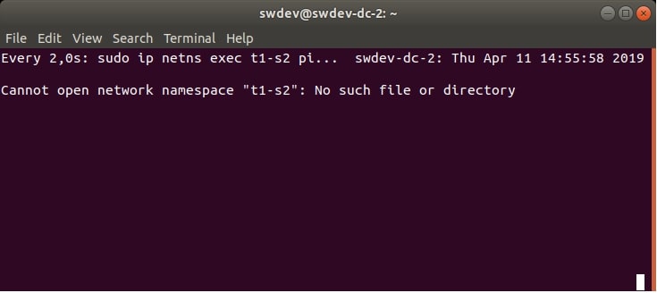
Figure 3 for DataCenter-2
The playbooks and the Ansible module made for this demo can be executed directly from CLI (see README.md) or used with AWX. We have made a workflow template in AWX, which executes playbooks in the correct order. You can see the graph of execution in Figure 4:
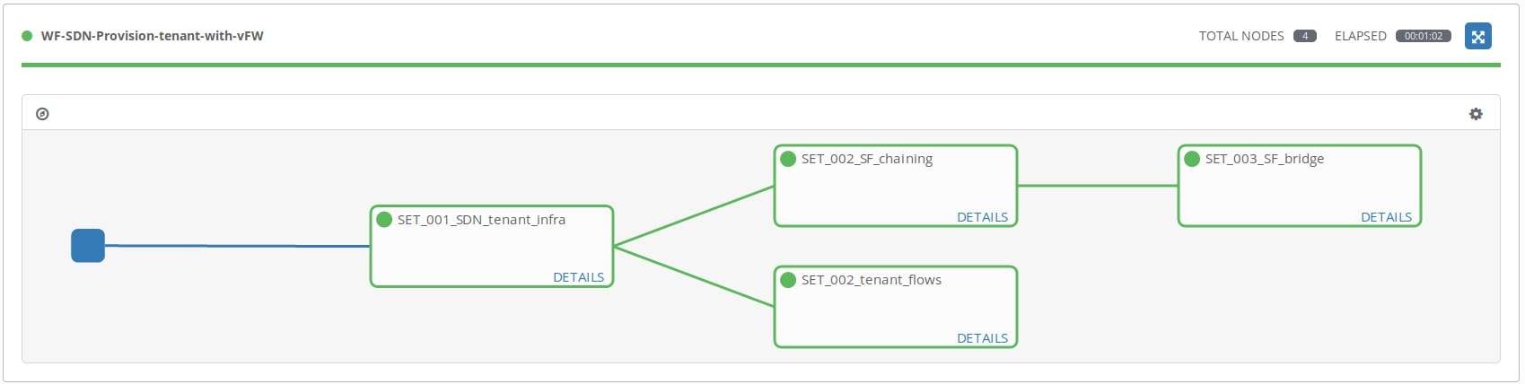
Figure 4: Graph of Playbook Execution
Tenant provisioning with SFC and vFW SF workflow execution
After successful execution of the workflow, we have a provisioned and configured network namespace in each DC VM, which is connected to the newly created bridge in each respective Open vSwitch. There’s also another namespace in DC-1 VM which is connected to the bridge while using two veth links.
- One link for traffic to/from tenant’s namespace
- One for traffic to/from the tunnel interface
The tunnel interface is also connected to the bridge and uses the VXLAN ID 123. The bridge in each Open vSwtich instance is configured by adding OpenFlow flows forwarding packets between ports of the bridge. The network namespace in the DC 1 VM called v-fw, is used for an SF, which implements a virtual firewall using Linux bridge (br0) and iptables.
After provisioning of the SF, both veth links are connected into the Linux bridge and iptables are empty so all packets (frames) can traverse the virtual firewall SF. The resulting system is displayed in Figure 5.
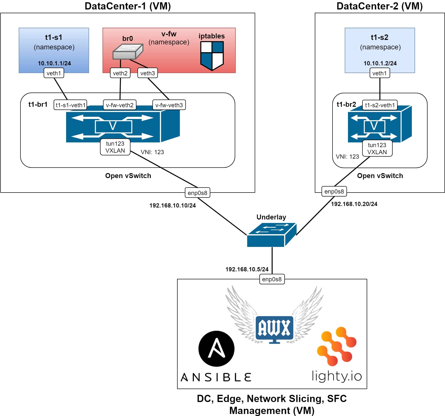
Figure 5 – Resulting structure of our system
Resulting system after successful provisioning
Now, if we would check the testing ping commands, we can see that the ICMP packets are able to reach the destination, see Figure 6. and Figure 7.
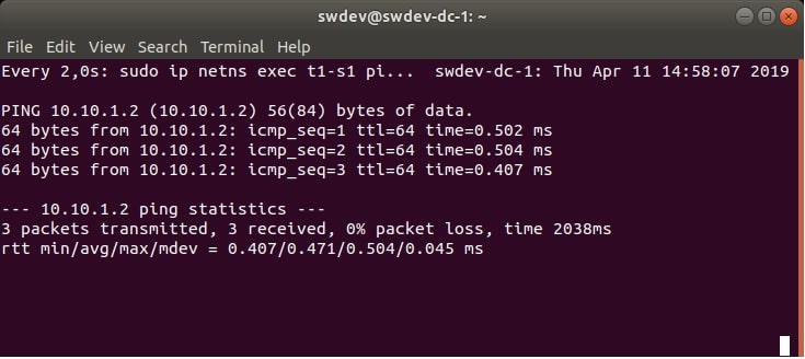
Figure 6 – Successful ping commands in each direction (DataCenter-1)
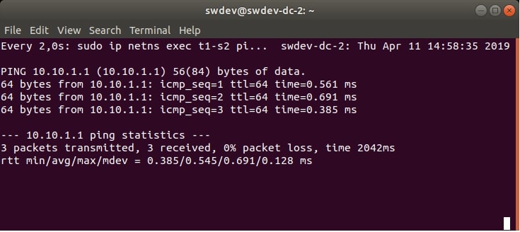
Figure 7 – Successful ping commands in each direction (DataCenter-2)
The Path of ICMP Packets
In Figure 8, there are details of OpenFlow flows configured during provisioning in each bridge in the Open vSwtich instances.
The ICMP packet is not the first packet in communication, initiated by the ping command. It is an ARP broadcast, which traverses the same path as ICMP packets.
Here’s a description of the path traversed by ICMP packets from t1-s1 to t1-s2:
- ICMP request message starting from the namespace t1-s1, with the destination in t1-s2. It is forwarded from veth1 interface of t1-s1 and received in the interface t1-s1-veth1 of the bridge t1-br1
- There is a configured flow, which forwards every single L2 frame (not only L3 packet) received at port t1-s1-veth1, to the port v-fw-veth2. This is connected into the v-fw namespace
- The packet is received at veth2 of v-fw and is forwarded by br0 to veth3. Since there aren’t any iptables rules configured yet, the packet is forwarded through veth3 outside the v-fw SF
- The packet is received at v-fw-veth3 port of t1-br1 and there is an applied rule for forwarding each packet (frame) received at v-fw-veth3, directly to the tun123 port
- The port tun123 is a VXLAN tunnel interface, with VNI (VXLAN Network Identifier) set to 123. Each L2 frame traversing the tun123 port is encapsulated into VXLAN frame (outer Ethernet, IP, UDP and VXLAN headers are added before the original – inner – L2 frame)
- Now the destination IP address of the packet becomes 192.168.10.20 (according to the configuration of the VXLAN tunnel interface) and is forwarded by the networking stack of the DC-1 VM’s host OS, through the enp0s8 interface to the underlying network
- The underlying network forwards the packet to DC-2 VM, through the enp0s8 and the host OS networking stack. It finally reaches the tun123 interface of the bridge t1-br2
- The VXLAN packet is decapsulated and the original ICMP packet is forwarded from tun123 to t1-s2-veth1, according to the OpenFlow flows in t1-br2
- Now, it is received in t1-s2 at the interface of veth1 and processed by the networking stack in the namespace. The ICMP echo reply is sent through the same path back to the t1-s1 in the DC-1 VM
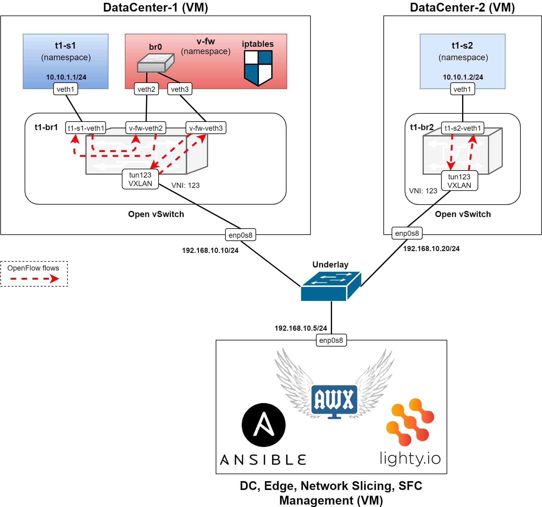
Figure 8: Detail of the OpenFlow flows configured in the bridges in Open vSwitch instances
Using the iptables as a Virtual Firewall
Now, we can use the Virtual Firewall SF and apply some iptables rules to the traffic, generated by the ping commands. Here is an example of the command, submitted at DC1 VM, which executes the iptables command in the v-fw namespace. The iptables command adds a rule to the FORWARD chain, which drops an ICMP echo (request) packets and the rule is applied at veth3 interface:
sudo ip netns exec v-fw iptables -A FORWARD -p icmp --icmp-type 8 -m state --state NEW,ESTABLISHED,RELATED -m physdev --physdev-in veth3 -j DROP
Result of this rule can be seen in Figure 9 and Figure 10. The ICMP traffic has now dropped. Not only in case of direction from DC2 to DC1, but also in the reverse direction (from DC1 to DC2), which also works.

Figure 9: The ping commands after the iptables role applied (DataCenter-1)
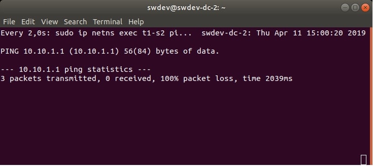
Figure 10: The ping commands after the iptables role applied (DataCenter-2)
Ansible playbooks & module
We’re going to take a closer look at the playbooks. These are used for the provisioning of the infrastructure above. We will follow the graph from Figure 4, where the workflow template execution is shown. The template only executes job templates, which are associated with exactly one playbook.
Each playbook made for this demo uses the same configuration structure, which has been designed to be easily extensible and re-usable for other scenarios, which use the same playbooks.
See the following block, showing the example configuration used for this demo. The same configuration in JSON format is stored in our repository, as cfg/cfg_example.json. Here are the main decisions, which will help us to achieve the desired re-usability:
- The configuration contains a list of configurations for each DC, called cfg_list. The playbook performs a lookup of the specific configuration, according to items “id” or “tun_local_ip“, which must match with the DC’s hostname or IP address respectively
- The single cfg_list item related to specific DC may include a configuration of SFC as “sf_cfg” item. If this configuration exists, then the SFC provisioning playbook (apb_set_chaining.yaml) will be executed for this DC (DC1 is an example in this demo)
- For the DC which doesn’t have specific SFC configuration, simple provisioning (apb_set_flows.yaml) is used, which interconnects tenant’s namespace with the tunnel interface (DC2 is an example in this demo)
ansible_sudo_pass: admin
sdn_controller_url: 'http://192.168.10.5:8888'
cfg_list:
  - id: swdev-dc-1
    bridge_name: t1-br1
    topology_id: 1
    of_ctrl: 'tcp:192.168.10.5:6633'
    server_name: t1-s1
    server_ip: 10.10.1.1
    server_veth: veth1
    server_of_port_id: 100
    tun_vxlan_id: 123
    tun_local_ip: 192.168.10.10
    tun_remote_ip: 192.168.10.20
    tun_of_port_id: 200
    sf_cfg:
      sf_id: v-fw
      con_left:
        name: veth2
        port_id: 10
      con_right:
        name: veth3
        port_id: 20
  - id: swdev-dc-2
    bridge_name: t1-br2
    topology_id: 2
    of_ctrl: 'tcp:192.168.10.5:6633'
    server_name: t1-s2
    server_ip: 10.10.1.2
    server_veth: veth1
    server_of_port_id: 100
    tun_vxlan_id: 123
    tun_local_ip: 192.168.10.20
    tun_remote_ip: 192.168.10.10
    tun_of_port_id: 200
Job Template Descriptions
Here is a short description of each job template & related playbook together, with the source code of the playbook. These include more detailed comments regarding the steps (tasks and roles) executed by each play of the playbook:
1. SET_001_SDN_tenant_infra is the job template which executes playbook apb_set_tenant.yaml. This playbook creates and connects tenant’s namespaces, bridges, veth links and VXLAN tunnel. See Figure 11, for how does the system look like after the execution of this playbook.
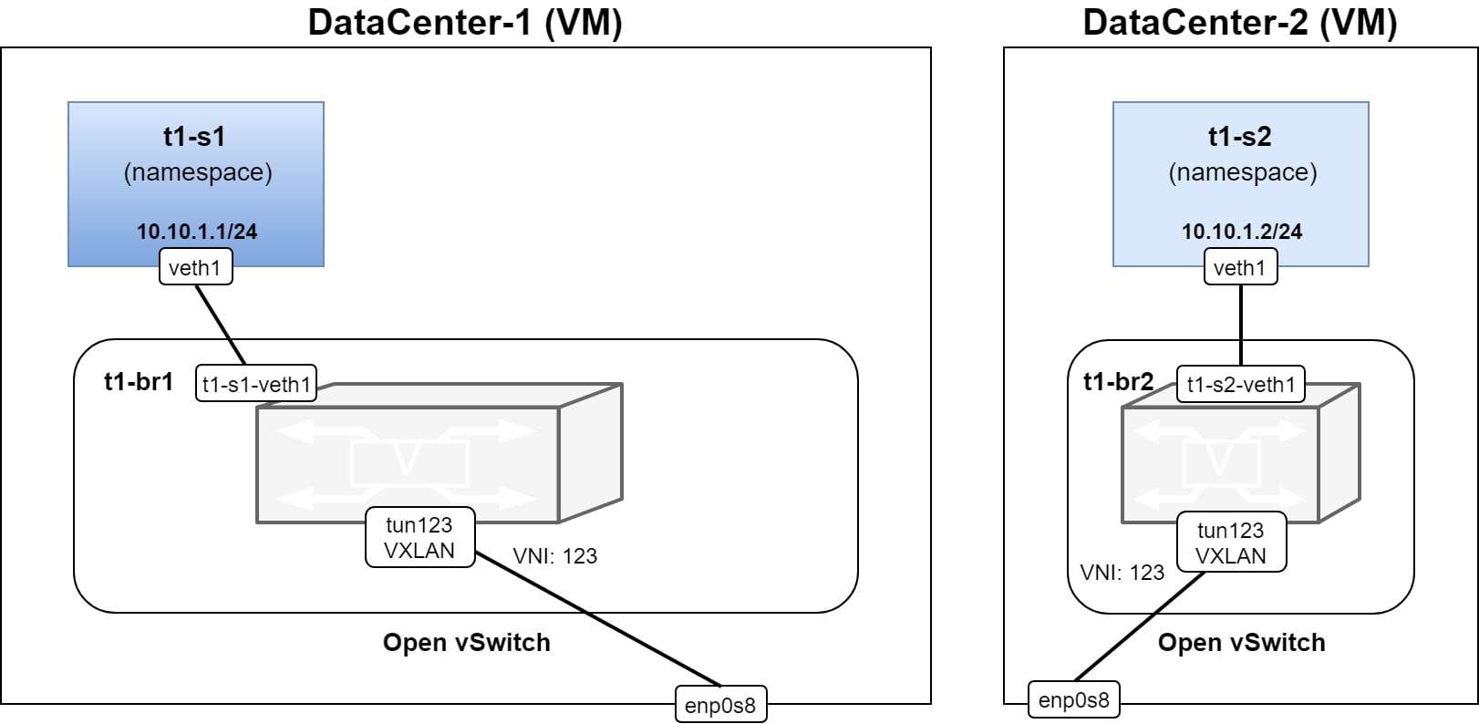
Figure 11: The state of the infrastructure after the execution of SET_001_SDN_tenant_infra template
# Read the configuration of the current host and create tenant's namespace and veth.
# Connect one end of the veth to the namespace and configure IP address and set the
# interface UP.
# Configure also OVS to use SDN controller as OVSDB manager.
- hosts: all
  serial: 1
  roles:
    - read_current_host_cfg
    - set_tenant_infra

# Send request to the SDN controller which connects the SDN controller to the OVS.
# Use SDN controller to create tenant's bridge in the OVS and connect
# the veth also into the bridge.
# Create also tunnel interface using VXLAN encapsulation and connect
# it to the bridge. (Linux kernel of the host OS will take care of
# forwarding packets to/from the tunnel)
- hosts: all
  connection: local
  serial: 1
  roles:
    - set_tenant_infra_cfg

# Setup OpenFlow connection from the bridge in OVS to the SDN controller.
# It must be done here because when the bridge connects to OpenFlow controller it deletes
# all interfaces and flows configured previously
- hosts: all
  serial: 1
  roles:
    - role: cfg_ovs_br_ctrl
      when: current_host_cfg.of_ctrl is defined
2. SET_002_SF_chaining executes playbook apb_set_chaining.yaml, which is executed for hosts which have specified the “sf_cfg” item in their configuration so in this demo it is DC1 only. This playbook runs in parallel with the SET_002_tenant_flows template and it creates a namespace for SF and required two veth links and connections. The playbook also configures the corresponding OpenFlow flows in the bridge.
See Figure 12, where you can see the difference after the successful execution.

Figure 12: The state of the infrastructure after the execution of SET_002_SF_chaining template
# Find the configuration for the current host and configure SFC infrastructure
# if the configuration contains item: sf_cfg
# The SFC infrastructure consists of two veth links and one namespace for the SF.
# Connect both links to the SF namespace by one side and to the tenant's bridge by
# the other side. Set links to UP state.
- hosts: all
  roles:
    - read_current_host_cfg
    - role: set_sf_chaining_infra
      vars:
        con_defs:
          - "{{ current_host_cfg.sf_cfg.con_left }}"
          - "{{ current_host_cfg.sf_cfg.con_right }}"
      when: current_host_cfg.sf_cfg is defined

# Use the SDN controller to configure OpenFlow flows which set up the forwarding
# of packets between ports in the tenant's bridge (veth links and the VXLAN tunnel).
- hosts: all
  connection: local
  roles:
    - role: set_sf_chaining_cfg
      when: current_host_cfg.sf_cfg is defined
3. SET_002_tenant_flows executes playbook apb_set_flows.yaml which is executed for hosts, which don’t have the “sf_cfg” item specified in their configuration, in this demo it is DC2. This playbook is executed parallel to SET_002_SF_chaining template and it just configures OpenFlow flows in the bridge, since everything has already been created and connected by SET_001_SDN_tenant_infra template. See Figure 13.
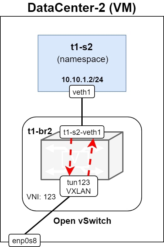
Figure 13: The state of the infrastructure after the execution of SET_002_tenant_flows template
# When the sf_cfg item of the current host's configuration is not defined then
# use the SDN controller and configure simple flows forwarding packets between
# veth link and the VXLAN tunnel interface.
- hosts: all
  connection: local
  roles:
    - read_current_host_cfg
    - role: set_tenant_flows
      when: current_host_cfg.sf_cfg is not defined
4. SET_003_SF_bridge is the job template, executing apb_set_bridge.yaml playbook. This creates a Linux bridge in the SF namespace for hosts with the “sf_cfg” defined. Both veth links of the SF namespace are connected to the Linux bridge. See Figure 14.
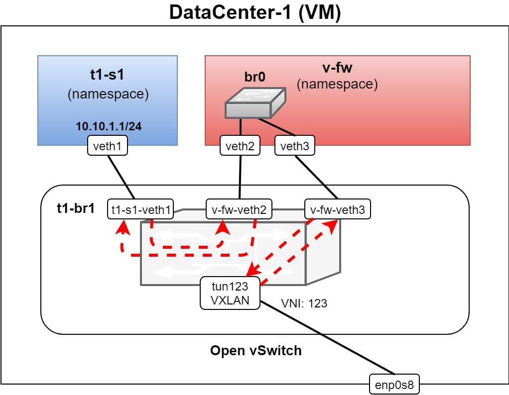
Figure 14: The state of the infrastructure after the execution of SET_003_bridge template
# Create linux bridge in the SF namespace and connect veth links to the
# linux bridge and set the bridge UP.
- hosts: all
  roles:
    - read_current_host_cfg
    - role: create_bridge_in_ns
      vars:
        net_ns_name: "{{ current_host_cfg.sf_cfg.sf_id }}"
        int_list:
          - "{{ current_host_cfg.sf_cfg.con_left.name }}"
          - "{{ current_host_cfg.sf_cfg.con_right.name }}"
      when: current_host_cfg.sf_cfg is defined
Playbooks used in this demo are not idempotent, so they can’t be executed successfully multiple times in a row. Instead, we have implemented two groups of playbooks.
One group sets all the stuff used in this demo. Another group deletes and un-configures everything and ignores possible errors of particular steps (tasks) so you can use it for cleaning of the setup, if necessary.
De-provisioning
We have also implemented three playbooks, which delete changes made by the provisioning playbooks. We have created a workflow in AWX running these playbooks in the correct order.
See the playbook sources and the README.md file for more information.
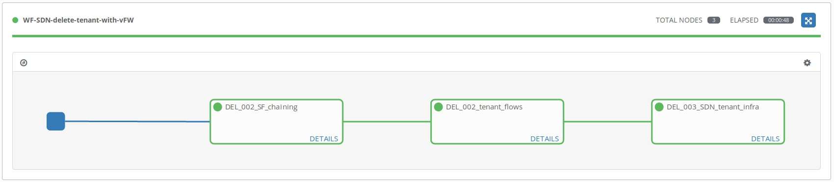
Figure 15: Tenant de-provisioning with SFC and vFW SF workflow execution
Multitenancy and isolation
In Figure 16, there’s an example where the second tenant is added. The tenant has two servers – one in each DC. The setup for the second tenant is simple, without SFC. As you can see the tenant has its own virtual bridge in each Open vSwitch instance.
IP addresses in the new tenant’s servers are identical with IP addresses in the first tenant servers. This is possible due to the traffic of each tenant being isolated, using extra virtual bridges and different VXLAN tunnels for each tenant or service.
The new tenant can be added, using the same group of playbooks and the same workflow template. The only thing which needs to be changed is the configuration used with the workflow template. See the example below in Figure 16.
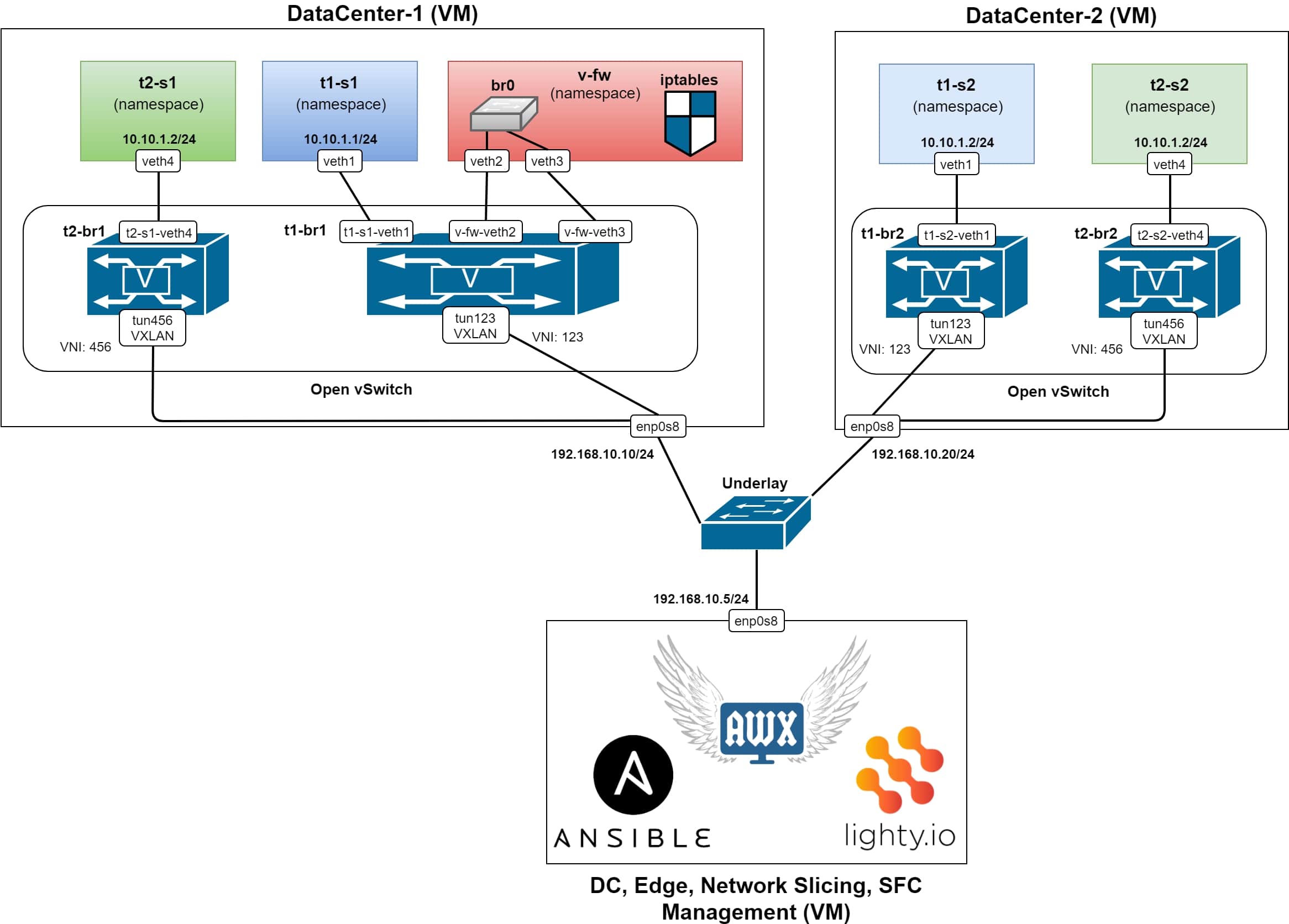
Figure 16: After the second tenant is added
Configuration example for the second tenant provisioning:
ansible_sudo_pass: admin
sdn_controller_url: 'http://192.168.10.5:8888'
cfg_list:
  - id: swdev-dc-1
    bridge_name: t2-br1
    topology_id: 3
    of_ctrl: 'tcp:192.168.10.5:6633'
    server_name: t2-s1
    server_ip: 10.10.1.1
    server_veth: veth4
    server_of_port_id: 100
    tun_vxlan_id: 456
    tun_local_ip: 192.168.10.10
    tun_remote_ip: 192.168.10.20
    tun_of_port_id: 200
  - id: swdev-dc-2
    bridge_name: t2-br2
    topology_id: 4
    of_ctrl: 'tcp:192.168.10.5:6633'
    server_name: t2-s2
    server_ip: 10.10.1.2
    server_veth: veth4
    server_of_port_id: 100
    tun_vxlan_id: 456
    tun_local_ip: 192.168.10.20
    tun_remote_ip: 192.168.10.10
    tun_of_port_id: 200
Role of the SDN controller
In this demo, we have used an SDN controller based on lighty.io for the configuration of Open vSwitch instances over OVSDB and OpenFlow protocols. The usage of the SDN controller brings the following benefits:
1. Unified REST HTTP API: The data of orchestrated devices (in this case Open vSwitch instances) which allows building upper layer services using this API (e.g. dashboards, analytics, automation and more).
One example of such an application is OFP (OpenFlow Manager), already mentioned in our previous blog.
In Figure 17, a screenshot of the Web UI of the OpenFlow is shown, shoving data into four OpenFlow bridges, which are configured after the second tenant has been added. You can see also details of specific flow matching, in port with the action of the type Output port.
2. Caching: The controller allows for caching of the state and configuration of the orchestrated device. The cached configuration can be persistently stored and pushed into the device after re-start of the managed device.
3. Addition logic implementation:e.g. monitoring, resource management, authorization, and accounting or decision making according to an overview of the whole network.
4. Additional deployment: Controllers can be deployed as a geo-distributed clustered registry of multi-vendor networking devices, of the whole core DC network, backbone networks or Edge DC networks.
This way, you can access all the data you need from all of your networking devices, on the path from the core DC to the edge and RAN (Radio Access Network).
5. Underlay Networking: The SDN controllers, based on lighty.io, can be used not only for configuration, orchestration, and monitoring of virtualized networking infrastructure and overlay networking, but also for underlay networking.
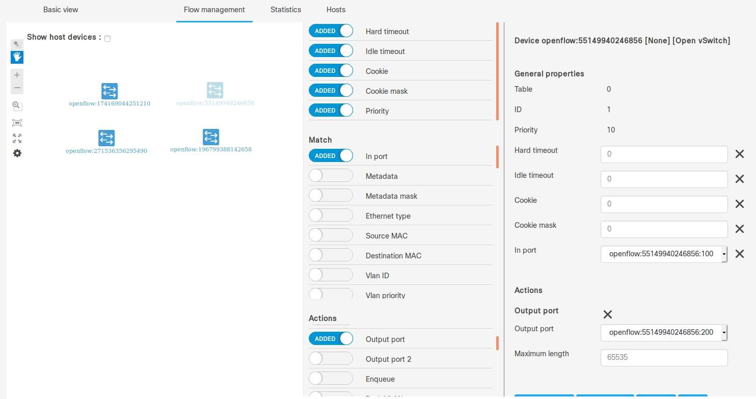
Figure 17: Screenshot of the OFM WEB UI, of the SDN controllers OpenFlow data
What have we done today?
We have demonstrated the usage of Ansible, AWX and an SDN controller based on lighty.io, for automation of provisioning of services for multi-tenant data centers.
We have implemented Ansible playbooks and modules for orchestration of virtualized networking infrastructure and provisioning of tenant’s containers (simulated by namespaces). The playbooks and the module can be re-used for multiple use cases and scenarios an can be extended according to specific needs.
You could see how to utilize Open vSwitch and its OpenFlow capable virtual bridges for the creation of an isolated, virtual network infrastructure and Service Function Chaining (SFC). Open vSwitch bridges can be replaced by any OpenFlow capable switch (virtual or bare metal) in real deployments in core data centers or at the edge.
Also, networking devices without OpenFlow support can be used if they implement some “SDN ready” management interface, e.g.: NETCONF, RESTCONF or gNMI.
All of the components used in this demo, including the SDN controller, can be easily integrated into microservices architectures and deployed as Cloud Native applications (services).
Adding upper layer services (dashboards, monitoring, automation, business logic, etc.) you can continuously build solutions for your SDN networks, edge computing or 5G networks.
You can contact us at https://pantheon.tech/
Explore our Pantheon GitHub.
Watch our YouTube Channel.

