In our previous blog post, we have introduced you to a Border Gateway Protocol Route-Reflector (BGP-RR) function in SDN controller based on lighty.io. In this article, we’re going to extend the BGP function of an SDN controller with an EVPN extension in the BGP control plane.
Functionality
This article will discuss BGP-EVPN functions in an SDN controller and how the lighty.io BGP function can replace existing legacy route-reflectors running in the service provider’s WAN/DC networks. BGP-EVPN provides:
- Advanced Layer 2 MAC and Layer 3 IP reachability information capabilities in control-plane
- Route-Type 2: advertising MAC/IP address, instead of traditional MAC learning mechanisms
- Route-Type 5: advertising the IP prefix subnet prefix route
We’re going to show you a BGP-EVPN IP subnet routing use-case
A BGP-EVPN control plane can also co-exist with various data-planes, such as MPLS, VXLAN, and PBB.
Use-case: Telecom Data-Center
In this blog, we’re going to show you the BGP-EVPN control plane working together with the VXLAN data plane. The perfect use case for this combination would be a telecom data center.
Virtual Extensible LAN (VXLAN) is an overlay technology for network virtualization. It provides Layer 2 extension over a shared Layer 3 underlay infrastructure network, by using the MAC address in an IP/User Datagram Protocol (MAC in IP/UDP) tunneling encapsulation. The initial IETF VXLAN standards defined a multicast-based flood-and-learn VXLAN without a control plane.
It relies on data-based flood-and-learn behavior for remote VXLAN tunnel endpoint (VTEP) peer-discovery and remote end-host learning. BGP-EVPN, as the control plane for VXLAN, overcomes the limitations of the flood-and-learn mechanism.
Test Bed
In this demo, we will use:
- five Docker containers & three Docker networks.
- Docker auto-generated user-defined bridge networks with mask /16
- Arista’s cEOS software, as we did in our previous demo
Remember, that an Arista cEOS switch creates an EtX port when starting up in the container, which is bridged to the EthX port in Docker.
These auto-generated EtX ports are accessible and configurable from cEOS Cli and on start are in default L2 switching mode. This means they don’t have an IP address assigned.
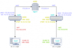
Well, let’s expand our previous demo topology with few more network elements. Here is a list of Docker containers used in this demo:
- leaf1 & leaf2: WAN switch & access/node
- host1 & host2: Ubuntu VM
- BGP-RR: BGP-EVPN Route Reflector
Here is a list of Docker user-defined networks used in this demo:
- net1 (172.18.0.0/16): connects leaf1 & host1
- net2 (172.19.0.0/16): connects leaf2 & host2
- net3 (172.20.0.0/16: connects leaf1, leaf2 & bgp-rr
Our Goal: Routing
At the end of this blog, we want to be able to reach IP connectivity between virtual machine host1 and host2. For that, we need BGP to advertise loopback networks and VLAN information between nodes.
In this example, we are using one AS-50.
To demonstrate route-reflector EVPN functionality leaf1 & leaf2 doesn’t make an IBGP pair but creates a pair with lighty-BGP instead. This will act as a route reflector. In VxLAN configuration we don’t set up flood vtep. This information should redistribute Route Routing to peers.
The container with lighty-BGP MUST NOT be used as a forwarding node since it doesn’t know the routing table.
Configuration
This demo configuration is prepared and tested on Ubuntu 18.04.2.
Docker Configuration
Before you start, please make sure that you have Docker (download instructions, use version 18.09.6 or higher) & Postman downloaded and installed.
1. Download lighty-BGP Docker image. PANTHEON.tech has its own
https://hub.docker.com/u/pantheontech
sudo docker pull pantheontech/lighty-rr:9.2.0-dev
2. Download the Docker image for Arista cEOS (v. 4.26.1F)
sudo docker import cEOS-lab.tar.xz ceosimage:4.26.1F
3. Download the Ubuntu image from DockerHub
sudo docker pull ubuntu:latest
4. Check the Docker images, successfully installed in the repository
sudo docker images
Preparing the Docker Environment
1. Create Docker networks
sudo docker network create net1
sudo docker network create net2
sudo docker network create net3
2. Check all Docker networks, that have been created
sudo docker network ls
3. Create containers in Docker
sudo docker create --name=bgp-rr --privileged -e INTFTYPE=eth -it pantheontech/lighty-rr:9.2.0-dev
sudo docker create --name=leaf1 --privileged -e INTFTYPE=eth -e ETBA=1 -e SKIP_ZEROTOUCH_BARRIER_IN_SYSDBINIT=1 -e CEOS=1 -e EOS_PLATFORM=ceoslab -e container=docker -i -t ceosimage:4.26.1F /sbin/init systemd.setenv=INTFTYPE=eth systemd.setenv=ETBA=1 systemd.setenv=SKIP_ZEROTOUCH_BARRIER_IN_SYSDBINIT=1 systemd.setenv=CEOS=1 systemd.setenv=EOS_PLATFORM=ceoslab systemd.setenv=container=docker
sudo docker create --name=leaf2 --privileged -e INTFTYPE=eth -e ETBA=1 -e SKIP_ZEROTOUCH_BARRIER_IN_SYSDBINIT=1 -e CEOS=2 -e EOS_PLATFORM=ceoslab -e container=docker -i -t ceosimage:4.26.1F /sbin/init systemd.setenv=INTFTYPE=eth systemd.setenv=ETBA=1 systemd.setenv=SKIP_ZEROTOUCH_BARRIER_IN_SYSDBINIT=1 systemd.setenv=CEOS=2 systemd.setenv=EOS_PLATFORM=ceoslab systemd.setenv=container=docker
sudo docker create --privileged --name host1 -i -t ubuntu:latest /bin/bash
sudo docker create --privileged --name host2 -i -t ubuntu:latest /bin/bash
4. Connect containers to Docker networks
sudo docker network connect net1 leaf1
sudo docker network connect net1 host1
sudo docker network connect net2 leaf2
sudo docker network connect net2 host2
sudo docker network connect net3 bgp-rr
sudo docker network connect net3 leaf1
sudo docker network connect net3 leaf2
5. Start all containers
sudo docker start leaf1
sudo docker start leaf2
sudo docker start host1
sudo docker start host2
sudo docker start bgp-rr
6. Enable permanent IPv4 forwarding in cEOS containers
sudo docker exec -it leaf1 /sbin/sysctl net.ipv4.conf.all.forwarding=1
sudo docker exec -it leaf2 /sbin/sysctl net.ipv4.conf.all.forwarding=1
7. Check, whether all Docker containers have started successfully
sudo docker container ls
Optional: Use this, if you’re looking for detailed information about running Docker containers (X is replaced by device/host number)
sudo docker container inspect [leaf[X] | bgp-rr | host[X]]
Preparing Ubuntu Environment
1. Get into the machine (X is replaced by device/host number)
sudo docker exec -it host[X] bash
2. Update the machine
apt-get update
3. Install the required packages
apt-get install iproute2
apt-get install iputils-ping
4. Exit the Docker Container (CTRL+D). Repeat steps 2 & 3.
Arista cEOS Switch configuration
Now, we will configure Arista cEOS switches. We will split the configuration of Arista cEOS Switches into several steps.
Click here for full configurations of Arista switches ‘leaf1‘ & ‘leaf2‘.
Ethernet interfaces & connectivity check
1. Go into the Arista switch leaf1
sudo docker exec -it leaf1 Cli
2. Set Privilege, and go to configure-mode
enable
configure terminal
3. Setup the switch’s name
hostname leaf1
4. Setup Ethernet interface. If you use more devices than your devices could be connected to another Ethernet
interface ethernet 2
no switchport
ip address 172.20.0.2/16
5. Check if BGP-RR is reachable from the configured interface.
- When you can’t ping ‘BGP-RR’, check if ‘leaf1′ and ‘BGP-RR’ are located in the same Docker network, or delete the previous step and try it on another Ethernet interface.
ping 172.20.0.4 source ethernet2
6. Repeat Step 5 for ‘leaf2′ & go into the Arista switch leaf2
sudo docker exec -it leaf2 Cli
enable
config t
hostname leaf2
interface ethernet 2
no switchport
ip address 172.20.0.3/16
ping 172.20.0.4 source ethernet2
Configuring the Border Gateway Protocol
We will have identical configurations for ‘leaf1′ & ‘leaf2′. Exceptions will be highlighted in the instructions below.
1. Enable BGP in Arista switch
- If you are still in the previous settings interface, go to the root of the Arista configuration by repeating the “exit” command.
service routing protocols model multi-agent
ip routing
2. Setup
- For ‘leaf2’, use the Router-ID ‘router-id 172.20.0.3‘
router bgp 50
router-id 172.20.0.2
neighbor 172.20.0.4 remote-as 50
neighbor 172.20.0.4 next-hop-self
neighbor 172.20.0.4 send-community extended
redistribute connected
redistribute attached-host
3. Setup EVPN in BGP
address-family evpn
neighbor 172.20.0.4 activate
Configuring VxLAN Interface & VLAN
We will have identical configurations for leaf1 & leaf2. Exceptions will be highlighted in the instructions below.
1. Enable VLAN with ID 10.
- Make sure that this command is typed in the root of Arista and not in BGP
- If you are still in the BGP configuration, use the command ‘exit’
vlan 10
2. Configure loopback 0, which will be used as a VTEP (VxLAN tunnel endpoint) for VxLAN.
- In ‘leaf2’, use IP ‘10.10.10.2/32’, instead of IP ‘10.10.10.1/32’
interface loopback 0
ip address 10.10.10.1/32
3. Configure VxLAN Interface
- Here we’ll set up loopback 0 as a VTEP and configure VNI (VXLAN Network Identifier) to 3322.
interface Vxlan1
vxlan source-interface Loopback0
vxlan udp-port 4789
vxlan vlan 10 vni 3322
vxlan learn-restrict any
4. Assign Ethernet interface to VLAN
interface Ethernet 1
switchport mode access
switchport access vlan 10
5. Share loopback 0 to BGP-RR
- In ‘leaf2‘, use IP ‘10.10.10.2/32’ instead of ‘10.10.10.1/32’
router bgp 50
address-family ipv4
network 10.10.10.1/32
6. Configure VLAN in BGP
- Here we share the information about VLAN to BGP-RR
router bgp 50
vlan 10
rd 50:3322
route-target both 10:3322
redistribute learned
7. Save your configuration with the ‘wr‘ command in both Arista devices and restart them with the command:
sudo docker restart leaf1 leaf2
lighty.io & BGP Route Reflector
In this part, we will add the Border Gateway Protocol configuration into the lighty.io BGP.
There is a lot to configure, so crucial parts are commented to break it down a little.
If we want to see the logs from lighty.io, we can attach them to the started container:
sudo docker attach bgp-rr
We can start the BGP-RR container with the command:
sudo docker start bgp-rr --attach
to see logs from the beginning. Afterward, send a PUT request to BGP-RR. We should see the following messages in the logs.
More RESTCONF commands can be found here.
Verify device state
Now, we will check if all configurations were set up successfully. We will also check if VxLAN is created and the Virtual PCs can ‘ping’ each other.
1. Check if EVPN BGP peering is established
leaf1(config)#sh bgp evpn summary
BGP summary information for VRF default
Router identifier 172.20.0.2, local AS number 50
Neighbor Status Codes: m - Under maintenance
  Neighbor         V  AS           MsgRcvd   MsgSent  InQ OutQ  Up/Down State  PfxRcd PfxAcc
  172.20.0.4       4  50                 3         6    0    0 00:00:09 Estab  0      0
leaf2(config)#sh bgp evpn summary
BGP summary information for VRF default
Router identifier 172.20.0.3, local AS number 50
Neighbor Status Codes: m - Under maintenance
  Neighbor         V  AS           MsgRcvd   MsgSent  InQ OutQ  Up/Down State  PfxRcd PfxAcc
  172.20.0.4       4  50               267       315    0    0 00:01:16 Estab  1      1
If your devices are in the state ‘Connected‘ or ‘Active‘, then you have checked this right after you sent a request to lighty.io. Usually, it takes, at most, one minute to establish a connection.
If you still see this state, then there could be something wrong with the BGP configuration. Please check your configuration in Arista CLI, by typing the command ‘show running-config‘ and compare it with the full Arista configuration above.
After you verify the Arista configuration, then there could be a problem in the BGP-RR container. This can be fixed by restarting the BGP-RR container.
2. Check ip route for available loopbacks from other devices
leaf1(config)#sh ip route
VRF: default
Codes: C - connected, S - static, K - kernel,
       O - OSPF, IA - OSPF inter area, E1 - OSPF external type 1,
       E2 - OSPF external type 2, N1 - OSPF NSSA external type 1,
       N2 - OSPF NSSA external type2, B I - iBGP, B E - eBGP,
       R - RIP, I L1 - IS-IS level 1, I L2 - IS-IS level 2,
       O3 - OSPFv3, A B - BGP Aggregate, A O - OSPF Summary,
       NG - Nexthop Group Static Route, V - VXLAN Control Service,
       DH - DHCP client installed default route, M - Martian,
       DP - Dynamic Policy Route

Gateway of last resort is not set

 C      10.10.10.1/32 is directly connected, Loopback0
 B I    10.10.10.2/32 [200/0] via 172.20.0.3, Ethernet2
 C      172.20.0.0/16 is directly connected, Ethernet2
leaf2(config)#sh ip route
VRF: default
Codes: C - connected, S - static, K - kernel,
       O - OSPF, IA - OSPF inter area, E1 - OSPF external type 1,
       E2 - OSPF external type 2, N1 - OSPF NSSA external type 1,
       N2 - OSPF NSSA external type2, B I - iBGP, B E - eBGP,
       R - RIP, I L1 - IS-IS level 1, I L2 - IS-IS level 2,
       O3 - OSPFv3, A B - BGP Aggregate, A O - OSPF Summary,
       NG - Nexthop Group Static Route, V - VXLAN Control Service,
       DH - DHCP client installed default route, M - Martian,
       DP - Dynamic Policy Route

Gateway of last resort is not set

 B I    10.10.10.1/32 [200/0] via 172.20.0.2, Ethernet2
 C      10.10.10.2/32 is directly connected, Loopback0
 C      172.20.0.0/16 is directly connected, Ethernet2
3. Check the VxLAN interface, if it creates and contains VTEP
leaf1#sh interfaces vxlan 1
Vxlan1 is up, line protocol is up (connected)
  Hardware is Vxlan
  Source interface is Loopback0 and is active with 10.10.10.1
  Replication/Flood Mode is headend with Flood List Source: EVPN
 Remote MAC learning via EVPN
  VNI mapping to VLANs
  Static VLAN to VNI mapping is
    [10, 3322]
  Note: All Dynamic VLANs used by VCS are internal VLANs.
        Use 'show vxlan vni' for details.
  Static VRF to VNI mapping is not configured
  Headend replication flood vtep list is:
    10 10.10.10.2
  VTEP address mask is None
leaf2(config)#sh interfaces vxlan 1
Vxlan1 is up, line protocol is up (connected)
  Hardware is Vxlan
  Source interface is Loopback0 and is active with 10.10.10.2
  Replication/Flood Mode is headend with Flood List Source: EVPN
 Remote MAC learning via EVPN
  VNI mapping to VLANs
  Static VLAN to VNI mapping is
    [10, 3322]
  Note: All Dynamic VLANs used by VCS are internal VLANs.
        Use 'show vxlan vni' for details.
  Static VRF to VNI mapping is not configured
  Headend replication flood vtep list is:
    10 10.10.10.1
  VTEP address mask is None
If you don’t see IP in the section ‘Headend replication flood vtep list is:‘, then the BGP-RR container is not started correctly. This problem can be fixed by removing the BGP-RR container and starting it again.
Restarting BGP-RR container
1. Stop the container
sudo docker stop bgp-rr
2. Remove BGP-RR container
sudo docker rm bgp-rr
3. Create a new container
sudo docker create --name=bgp-rr --privileged -e INTFTYPE=eth -it pantheontech/lighty-rr:9.2.0-dev
4. Connect BGP-RR to docker network
sudo docker network connect net3 bgp-rr
5. Start the container again
sudo docker start bgp-rr
Optional: If you want to see logs from light.io, attached them to the container:
sudo docker attach bgp-rr
Testing IP Connectivity
If everything worked out, we can test IP connectivity in a virtual PC.
1. Open Virtual PC host1
sudo docker exec -it host1 bash
2. Setup IP address for this device
ip addr add 31.1.1.1/24 dev eth1
3. Perform the same configuration at host2
sudo docker exec -it host1 bash
ip addr add 31.1.1.2/24 dev eth1
4. Try to ping host2 to host1
ping 31.1.1.1
root@e344ec43c089:/# ip route
default via 172.17.0.1 dev eth0
31.1.1.0/24 dev eth1 proto kernel scope link src 31.1.1.2
172.17.0.0/16 dev eth0 proto kernel scope link src 172.17.0.5
172.19.0.0/16 dev eth1 proto kernel scope link src 172.19.0.3

root@e344ec43c089:/# hostname -I
172.17.0.5 172.19.0.3 31.1.1.2

root@e344ec43c089:/# ping 31.1.1.1
PING 31.1.1.1 (31.1.1.1) 56(84) bytes of data.
64 bytes from 31.1.1.1: icmp_seq=1 ttl=64 time=114 ms
64 bytes from 31.1.1.1: icmp_seq=2 ttl=64 time=55.5 ms
64 bytes from 31.1.1.1: icmp_seq=3 ttl=64 time=53.0 ms
64 bytes from 31.1.1.1: icmp_seq=4 ttl=64 time=56.1 ms
^C
--- 31.1.1.1 ping statistics ---
4 packets transmitted, 4 received, 0% packet loss, time 3005ms
rtt min/avg/max/mdev = 53.082/69.892/114.757/25.929 ms
When we go back to the Arista switch, we can check routed MAC address information.
leaf1#sh mac address-table
          Mac Address Table
------------------------------------------------------------------

Vlan    Mac Address       Type        Ports      Moves   Last Move
----    -----------       ----        -----      -----   ---------
  10    0242.211d.8954    DYNAMIC     Et1        1       0:00:54 ago
  10    0242.8b29.b7ea    DYNAMIC     Vx1        1       0:00:40 ago
  10    0242.ac12.0003    DYNAMIC     Et1        1       0:00:14 ago
  10    0242.ac13.0003    DYNAMIC     Vx1        1       0:00:13 ago
  10    ce9a.ca0c.88a1    DYNAMIC     Et1        1       0:00:54 ago
Total Mac Addresses for this criterion: 5

          Multicast Mac Address Table
------------------------------------------------------------------

Vlan    Mac Address       Type        Ports
----    -----------       ----        -----
Total Mac Addresses for this criterion: 0
leaf2#sh mac address-table
          Mac Address Table
------------------------------------------------------------------

Vlan    Mac Address       Type        Ports      Moves   Last Move
----    -----------       ----        -----      -----   ---------
  10    0242.211d.8954    DYNAMIC     Vx1        1       0:00:48 ago
  10    0242.8b29.b7ea    DYNAMIC     Et1        1       0:01:03 ago
  10    0242.ac12.0003    DYNAMIC     Vx1        1       0:00:22 ago
  10    0242.ac13.0003    DYNAMIC     Et1        1       0:00:22 ago
  10    ce9a.ca0c.88a1    DYNAMIC     Vx1        1       0:00:48 ago
Total Mac Addresses for this criterion: 5

          Multicast Mac Address Table
------------------------------------------------------------------

Vlan    Mac Address       Type        Ports
----    -----------       ----        -----
Total Mac Addresses for this criterion: 0
Conclusion
We have successfully shown the lighty.io BGP functionality, which can replace legacy Route-Reflectors. This situation can be applied to telecom data centers and other use-cases. It demonstrates lighty.io’s versatility and usability. Contact us for more information!
Peter Šuňa & Peter Lučanský
You can contact us at https://pantheon.tech/
Explore our Pantheon GitHub.
Watch our YouTube Channel.

![[Case Study] High-performance Golang and VPP integration for Cloud-Native firewalls](https://pantheontech1.b-cdn.net/wp-content/uploads/2026/07/govpp_firewall.jpg)
![[Case Study] From R&D prototype to global commercial success](https://pantheontech1.b-cdn.net/wp-content/uploads/2026/07/rd_to_success.jpg)
![[Case Study] Automating bandwidth optimization and SRTE policy management](https://pantheontech1.b-cdn.net/wp-content/uploads/2026/07/bandwith_auto.jpg)