The lighty.io RNC (RESTCONF-NETCONF) application allows to easily initialize, start and utilize the most used OpenDaylight services and optionally add custom business logic.
This pre-packed container image served as a RESTCONF – NETCONF bridge for communication between the ONAP component CDS and Cisco® NSO.
Inside the app, we provide a pre-prepared Helm chart that can be easily used for Kubernetes deployment. This tutorial explains the step-by-step deployment of the lighty.io RNC application with Helm 2/3 and a custom, local Kubernetes engine.
Read the complete tutorial:
You will learn how to deploy the lighty.io RNC app via Helm 2 or Helm 3. While developers might still prefer to use HELM2, we have prepared scenarios for deployment in both versions of this Kubernetes package manager.
It is up to you, which Kubernetes engine you will pick for this deployment. We will be using and going through the installation of the microk8s Local Kubernetes engine.
Helm 2: Condition is to use k8s versions 1.21 or lower
Helm 3: Condition is to use k8s version 1.22 and higher
Likewise, we will show you how to simulate NETCONF devices through another lighty.io tool. The tutorial will finish by showing you simple CRUD operations for testing the lighty.io RNC App.
Why lighty.io?
PANTHEON.tech’s enhanced OpenDaylight based software offers significant benefits in performance, agility, and availability.
lighty.io offers a modular and scalable architecture, allowing dev-ops greater flexibility to deploy only those modules and libraries that are required for each use-case. This means that lighty.io is not only more lightweight at run time, but also more agile at development and deployment time.
And since only the minimum required set of components and libraries is present in a deployment at runtime, stability is enhanced as well.
Due to its modular capability, lighty.io provides a stable & scalable network controller experience, ideal for production deployments, enabling the burgeoning multitude of 5G/Edge use cases.
Create, validate and visualize the YANG data model of their application, without the need to call any other external tool – just by using the lighty.io framework.
YANGinator | Validate YANG files in IntelliJ
Built for one of the most popular IDEs, YANGinator is a plugin for validating YANG files without leaving your IDEs window!
We encourage you to read through over 28 original posts on our webpage. The topics range from explanations of recent network trends to interesting use-cases for enterprises.
The ultimate network orchestration tool for your enterprise network. This Smart Automated Net/Ops & Dev/Ops platform orchestrates your networks with a user-friendly UI. Manage hundreds to thousands of individual nodes with open-source tech and enterprise support & integration.
On the 11th of November, Orange hosted a webinar with The Linux Foundation, showcasing their production deployment of ONAP to automate their IP/MPLS transport network infrastructure.
PANTHEON.tech is extremely proud to see their OpenDaylight based lighty.io project, included in this, Orange’s first, successful production ONAP deployment. lighty.io is an open-source project developed and supported by PANTHEON.tech.
Open-Source Matters
Orange’s vision and target are to move from a closed IT architecture to an open platform architecture based on the Open Digital Framework, a blueprint produced by members of TMForum. ONAP provides ODP compliant functional blocks to cover the delivery of many use-cases like service provisioning of 5G transport, IP, fixed access, microwave, optical networks services, as well as CPE management, OS upgrades, and many others.
Why lighty.io?
The SDN-C is the networkcontroller component of ONAP – managing, assigning, and provisioning network resources. It is based on OpenDaylight, with additional Directed Graph Execution capabilities. However, lighty.io, PANTHEON.tech’s enhanced OpenDaylight based software, offers significant benefits in performance, agility, and availability, taking SDN-C to another level.
With increased functionality to upgrade dependencies and packaged use-case-based applications, lighty.io brings Software-Defined Networking to a Cloud-Native environment.
lighty.io offers a modular and scalable architecture, allowing dev-ops greater flexibility to deploy only those modules and libraries that are required for each use-case. This means that lighty.io is not only more lightweight at run time, but also more agile at development and deployment time.
And since only the minimum required set of components and libraries is present in a deployment at runtime, stability is enhanced as well.
Due to its modular capability, lighty.io provides a stable & scalable network controller experience, ideal for production deployments, enabling the burgeoning multitude of 5G/Edge use cases.
A reduced codebase footprint and packaging makes lighty.io more:
Lightweight
Agile
Stable
Secure
Scalable
PANTHEON.tech also provides other complementary tools, plugins, and additional features, like:
Orange Egypt uses ONAP as a northbound, higher-level orchestration, for L3VPN service provisioning.
The user leverages a GUI to enter network service parameters. The request is then submitted to the ONAP Service Orchestrator (SO), powered by Camunda‘s BPMN workflow engine, through a REST API and custom-designed workflow is executed.
Afterward, an instantiated ONAP SO workflow triggers the ONAP Controller Design Studio (CDS) using a REST API to run custom blueprint packages to start the provisioning of L3VPN network services.
In this production deployment, lighty.io is used for communication between CDS and Cisco NSO. The application used in the ONAP production deployment is lighty-RNC – a pre-packaged container image, providing a RESTCONF-NETCONF bridge.
CDS assigns required resources (IP + VLAN) from NETBOX and lighty.io secret from Vault. After successful allocation of needed resources by CDS, lighty.io then sends the information to Cisco NSO to configure devices via a NETCONF session.
Orange demonstrated ONAP in an IP/MPLS backbone automation use-case, but that is just the beginning. ONAP is already starting to look into automation and SDN control of microwave and optical networks, paving the way for other operators to deploy ONAP in their use cases.
In 2001, a friend asked me if I would like to start a company with him. Word got out, so in the end, we were four – a bunch of acquaintances who didn’t exactly know what they were doing. Among other activities, we did not have time for the company and this was fully reflected in the first financial statements.
In 2004, after graduating from university, I turned my attention back to the company. I had the ambition to run it and over time we agreed to rewrite all shares to me and my sister. It was then, that Pantheon became a FAMILY COMPANY.
In addition to solving common system integrations, we started by selling used hardware – our goal was retail. At that time, however, prices and margins began to fall sharply, so we switched to wholesale. We exported to the Middle East, Asia, or Africa. We gradually added ATMs, that left Slovakia for Hong Kong and Turkey.
I enjoyed this job. Pantheon had about 5 employees at the time. However, margins continued to decline and there was an opportunity to focus on software development. I did not say no to the offer – there was significantly more money in this area. At the time, I didn’t even think about whether I was going to “build a big business” or where I want to be in 20 years. It is very fashionable today to talk about it this way, but in reality, I would be lying.
In 2009, we signed our first contract in Silicon Valley. We were a good group, who enjoyed their jobs. In 2011 we opened our first office in the US and in 2013, we started to expand to Banská Bystrica & Žilina.
Thanks to the growth, we were able to gain new experience and transform it into our own product portfolio in the field of network technologies, such as lighty.io, CDNF.io, SandWork, and EntGuard. We also managed to create a comprehensive HR system, Chronos, which facilitates the management of all personnel processes, including records and attendance management of all employees.
We had more people at the peak than we could manage. It’s time to cut back a bit and make quality a top priority. Even today, we are still working on clearly communicating to employees, what work environment we support through our expectations and their benefits.
This year, we celebrate 20 years since our inception. During that time, we repaid our debts and took the opportunity to grow. We learned that growth is not directly proportional to the quality and we prefer to stay smaller, but more valuable for us and our clients. We have found that we will always look for and prefer people who are not afraid of challenges and self-reflection.
I am proud of our journey until now and I look forward to everything that comes. Mainly from the product point of view.
The 15th release of lighty.io is here, bringing a bunch of new features and even more improvements for you to create your SDN controller.
Parallel to working on OpenDaylight – PANTHEON.tech being the largest contributor to the OpenDaylight Phosphorus release – our team was working hard on releasing the newest version of lighty.io.
Of course, lighty.io adopted the latest Phosphorus upstream. So let’s have a look at what else is new in lighty.io 15!
[Feature] lighty.io gNMI Module – Simulator
The latest addition to lighty.io modules is the gNMI module for device simulation. This simulator simulates gNMI devices driven by gNMI proto files, with a datastore defined by a set of YANG models. gNMI is used for the configuration manipulation and state retrieval of gNMI devices.
The gNMI Simulator supports SONiC gNOI, to the extent of the following gNOI gRPCs:
Hand-in-hand, the lighty.io RESTCONF gNMI App now provides Docker & Helm support, for deployment via Kubernetes.
The example shows a gNMI south-bound interface, utilized with a RESTCONF north-bound interface to manage gNMI devices on the network.
This example works as a standalone SDN controller and is capable of connecting to gNMI devices and exposing connected devices over RESTCONF north-bound APIs.
Enterprises require workflows to understand internal processes, how they apply to different branches, and divide responsibility to achieve a common goal. Using a workflow enables to pick & choose, which models are required.
Although there are many alternatives, BPMN is a standard widely used across several fields to graphically depict business processes and manage them.
Notable, although underrated, are its benefits for network administrators. BPMN enables network device management & automation, without having to fully comprehend the different programming languages involved in each task.
What is BPMN?
The Business Process Model & Notation (BPMN) standard graphically represents specifics of business processes in a business process model. In cooperation with the Camunda platform, which provides its own BPMN engine, it can do wonders with network orchestration automation.
BPMN lets enterprises graphically depict internal business procedures and enables companies to render these procedures in a standardized manner. Using BPMN removes the need for software developers to adjust business logic since the entire workflow can be managed through a UI.
In the case of network management, it provides a level of independence, abstracted from the network devices themselves.
This logic behind how business processes are standardized as workflows is present in the Open Network Automation Platform (ONAP) as well.
What is ONAP?
ONAP is an orchestration and automation framework, featuring an open-source software concept, that is robust, real-time, policy-driven, for physical and virtual network functions.
Camunda is an open-source platform, used in the ONAP Service Orchestrator – where it serves as one of the core components of the project to handle BPMN 2.0 process flows.
The SO component is mostly composed of Java & Groovy code, including a Camunda BPMN code-flow.
PANTHEON.tech circumvents the need for SO and uses the Camunda BPMN engine directly. This resulted in a project with SO functionality, without the additional SO components – sort of a microONAP concept.
Features: Camunda & BPMN
The business process modeling is a single action of network orchestration. As with any project integration, it is important to emphasize the project’s strong points, which enabled us to achieve a successful use case.
Benefits of Camunda/BPMN
Automation: BPMN provides a library of reusable boxes, which make their use more accessible by avoiding/hiding unnecessary complexity
Performant BPMN Engine: the engine provides good out-of-the-box performance, with a variety of operator/DevOps UI tools, as well as BPMN modeling tools
User Interface: OOTB user interface, with the option of creating a custom user interface
DevOps: easy manipulation & development of processes
Scalability: in terms of performance tuning and architecture development for lots of tasks
Interoperability: extensible components, REST integration, or script hooks for Groovy, JavaScript & more
REST API: available for BPMN engine actions
Exceptional Error Handling
Scalability: tasks with high execution cadence can be externalized and be implemented as scalable microservices. That provides not only scalability to the system itself but can be applied to the teams and organizations as well
Process tracking: the execution of the process is persisted and tracked, which helps with system recovery and continuation of the process execution in partial and complete failure scenarios.
What PANTHEON.tech had to mitigate is, for example, parallelism – running several processes at once. Timing estimation limits the high precision configuration of network devices. Imagine you want to automate a process starting with Task 1. After a certain time, Task 2 takes effect. Timers in BPMN however need manual configuration to tune the interval between jobs & processes.
Our deep dive into this topic resulted in a concept for automating network configurations in spine-leaf data centers, using a lightweight ONAP SO architecture alternative.
Use Case: Virtual Network Configuration in Spine-Leaf Data Centers
PANTHEON.tech has achieved, that the design of this use-cases custom architecture is fully functional and meets the required criteria – to fully adopt network automation in a demanding environment.
Our use-case shows how BPMN can be used as a network configuration tool in, for example, data centers. In other words – how ONAP’s SO and lighty.io could be used to automate your data center.
If you are interested in this use case, make sure to contact us and we can brief you on the details.
The lighty.io gNMI RESTCONF app allows for easy manipulation of gNMI devices. PANTHEON.tech has open-sourced the gNMI RESTCONF app for lighty.io, to increase the capabilities of lighty.io for different implementations and solutions.
Imagine CRUD operation on multiple gNMI devices, managed by one application – lighty.io. All requests towards the gNMI devices are executed by RESTCONF operations, while the response is formatted in JSON.
The most important lighty.io components used in the lighty.io gNMI RESTCONF application are:
lighty.io Controller – provides core OpenDaylight services (MD-SAL, YANG Tools, Global Schema Context & more) that are required for other services or plugins
lighty.io RESTCONF Northbound – provides the RESTCONF interface, used for communication with the application, via the RESTCONF protocol over HTTP
lighty.io gNMI Southbound – acts as the gNMI client. Manages connections to gNMI devices and gNMI communication. Currently supported gNMI capabilities are Get & Set
Prerequisites
To build and start the lighty.io gNMI RESTCONF application locally, you need:
Java 11 or later
Maven 3.5.4 or later
Custom Configuration
Before the lighty gNMI RESTCONF app creates a mount point for communicating with the gNMI device, it is necessary to create a schema context. This schema context is created, based on the YANG files which the device implements. These models are obtained via the gNMI Capability response, but only model names and versions are actually returned. Thus, we need some way of providing the content of the YANG model.
The way of providing content for the YANG file, so lighty.io gNMI RESTCONF can correctly create schema context, is to:
add a parameter to the RCGNMI app .json configuration
use upload-yang-model RPC
Both of these options will load the YANG files into the data-store, from which the ligthy.io gNMI RESTCONF reads the model, based on its name and version, obtained in the gNMI Capability response.
YANG Model Configuration as a Parameter
Open the custom configuration example in src/main/resources/example_config.json
Add custom gNMI configuration in root, next to the controller or RESTCONF configuration
```
"gnmi": {
"initialYangsPaths" : [
"INITIAL_FOLDER_PATH"
]
}
```
3. Change `INITIAL_FOLDER_PATH`, from JSON block above, to folder path, which contains YANG models you wish to
load into datastore. These models will be then automatically loaded on startup.
2) Add yang model with RPC request to running app
- 'YANG_MODEL' - Should have included escape characters before each double quotation marks character.
```
curl --request POST 'http://127.0.0.1:8888/restconf/operations/gnmi-yang-storage:upload-yang-model' \
--header 'Content-Type: application/json' \
--data-raw '{
"input": {
"name": "openconfig-interfaces",
"semver": "2.4.3",
"body": "YANG_MODEL"
}
}'
```
Start the gNMI RESTCONF Example App
1. Build the project using:
mvn clean install
2. Go to the target directory:
cd lighty-rcgnmi-app/target
3. Unzip example application bundle:
unzip lighty-rcgnmi-app-14.0.1-SNAPSHOT-bin.zip
4. Go to the unzipped application directory:
cd lighty-rcgnmi-app-14.0.1-SNAPSHOT
5. To start the application with a custom lighty.io configuration, use arg -c. For a custom initial log4j configuration, use the argument -l:
Certificates, used for connecting to a device, can be stored inside the lighty-gnmi data store. The certificate key and passphrase are encrypted before they are stored inside the data store.
After registering the certificate key and passphrase, it is not possible to get decrypted data back from the data store.
To update the already existing certificates, use the request for registering a new certificate with the keystore-id you wish to update.
Connecting a gNMI Device
To establish a connection and communication with the gNMI device via RESTCONF, one needs to add a new node to gnmi-topology. This is done by sending the appropriate requests (examples below) with a unique node-id.
The connection parameters are used to specify connection parameters and the client’s (lighty gNMI RESTCONF) way of authenticating.
The property connection-type is enum and can be set to two values:
INSECURE: Skip TLS validation with certificates
PLAINTEXT: Disable TLS validation
When the device requires the client to authenticate with registered certificates, remove the connection-type property. Then, add the keystore-id property with the ID of the registered certificates.
If the device requires username/password validation, then fill username and password in the credentials container. This container is optional.
In case the device requires additional parameters in the gNMI request/response, there is a container called extensions-parameters, where a defined set of parameters can be optionally included in the gNMI request and response. Those parameters are:
overwrite-data-type is used to overwrite the type field of gNMI GetRequest.
use-model-name-prefix is used when the device requires a module prefix in the first element name of gNMI request path
path-target is used to specify the context of a particular stream of data and is only set in prefix for a path
curl --request GET 'http://127.0.0.1:8888/restconf/data/network-topology:network-topology/topology=gnmi-topology/node=node-id-1'
[Example] RESTCONF gNMI GetRequest
curl --location --request GET 'http://127.0.0.1:8888/restconf/data/network-topology:network-topology/topology=gnmi-topology/node=node-id-1/yang-ext:mount/openconfig-interfaces:interfaces'
In our previous blog post, we have introduced you to a Border Gateway Protocol Route-Reflector (BGP-RR) function in SDN controller based on lighty.io. In this article, we’re going to extend the BGP function of an SDN controller with an EVPN extension in the BGP control plane.
Functionality
This article will discuss BGP-EVPN functions in an SDN controller and how the lighty.io BGP function can replace existing legacy route-reflectors running in the service provider’s WAN/DC networks. BGP-EVPN provides:
Advanced Layer 2 MAC and Layer 3 IPreachability information capabilities in control-plane
Route-Type 2: advertising MAC/IP address, instead of traditional MAC learning mechanisms
Route-Type 5: advertising the IP prefix subnet prefix route
We’re going to show you a BGP-EVPN IP subnet routing use-case
A BGP-EVPN control plane can also co-exist with various data-planes, such as MPLS, VXLAN, and PBB.
Use-case: Telecom Data-Center
In this blog, we’re going to show you the BGP-EVPN control plane working together with the VXLAN data plane. The perfect use case for this combination would be a telecom data center.
Virtual Extensible LAN (VXLAN) is an overlay technology for network virtualization. It provides Layer 2 extension over a shared Layer 3 underlay infrastructure network, by using the MAC address in an IP/User Datagram Protocol (MAC in IP/UDP) tunneling encapsulation. The initial IETF VXLAN standards defined a multicast-based flood-and-learn VXLAN without a control plane.
It relies on data-based flood-and-learn behavior for remote VXLAN tunnel endpoint (VTEP) peer-discovery and remote end-host learning. BGP-EVPN, as the control plane for VXLAN, overcomes the limitations of the flood-and-learn mechanism.
Test Bed
In this demo, we will use:
five Docker containers & three Docker networks.
Docker auto-generated user-defined bridge networks with mask /16
Arista’s cEOS software, as we did in our previous demo
Remember, that an Arista cEOS switch creates an EtX port when starting up in the container, which is bridged to the EthX port in Docker.
These auto-generated EtX ports are accessible and configurable from cEOS Cli and on start are in default L2 switching mode. This means they don’t have an IP address assigned.
Well, let’s expand our previous demo topology with few more network elements. Here is a list of Docker containers used in this demo:
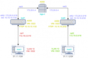
leaf1 & leaf2: WAN switch & access/node
host1 & host2: Ubuntu VM
BGP-RR: BGP-EVPN Route Reflector
Here is a list of Docker user-defined networks used in this demo:
At the end of this blog, we want to be able to reach IP connectivity between virtual machine host1 and host2. For that, we need BGP to advertise loopback networks and VLAN information between nodes.
In this example, we are using one AS-50.
To demonstrate route-reflector EVPN functionality leaf1 & leaf2 doesn’t make an IBGP pair but creates a pair with lighty-BGP instead. This will act as a route reflector. In VxLAN configuration we don’t set up flood vtep. This information should redistribute Route Routing to peers.
The container with lighty-BGP MUST NOT be used as a forwarding node since it doesn’t know the routing table.
Configuration
This demo configuration is prepared and tested on Ubuntu 18.04.2.
Docker Configuration
Before you start, please make sure that you have Docker (download instructions, use version 18.09.6 or higher) & Postman downloaded and installed.
1. Downloadlighty-BGP Docker image. PANTHEON.tech has its own
Now, we will configure Arista cEOS switches. We will split the configuration of Arista cEOS Switches into several steps.
Click here for full configurations of Arista switches ‘leaf1‘ & ‘leaf2‘.
Ethernet interfaces & connectivity check
1. Go into the Arista switch leaf1
sudo docker exec -it leaf1 Cli
2. Set Privilege, and go to configure-mode
enable
configure terminal
3. Setup the switch’s name
hostname leaf1
4. Setup Ethernet interface. If you use more devices than your devices could be connected to another Ethernet
interface ethernet 2
no switchport
ip address 172.20.0.2/16
5. Check if BGP-RR is reachable from the configured interface.
When you can’t ping ‘BGP-RR’, check if ‘leaf1′ and ‘BGP-RR’ are located in the same Docker network, or delete the previous step and try it on another Ethernet interface.
ping 172.20.0.4 source ethernet2
6. Repeat Step 5 for ‘leaf2′ & go into the Arista switch leaf2
sudo docker exec -it leaf2 Cli
enable
config t
hostname leaf2
interface ethernet 2
no switchport
ip address 172.20.0.3/16
ping 172.20.0.4 source ethernet2
Configuring the Border Gateway Protocol
We will have identical configurations for ‘leaf1′ & ‘leaf2′. Exceptions will be highlighted in the instructions below.
1. Enable BGP in Arista switch
If you are still in the previous settings interface, go to the root of the Arista configuration by repeating the “exit” command.
service routing protocols model multi-agent
ip routing
2. Setup
For ‘leaf2’, use the Router-ID ‘router-id 172.20.0.3‘
Now, we will check if all configurations were set up successfully. We will also check if VxLAN is created and the Virtual PCs can ‘ping’ each other.
1. Check if EVPN BGP peering is established
leaf1(config)#sh bgp evpn summary
BGP summary information for VRF default
Router identifier 172.20.0.2, local AS number 50
Neighbor Status Codes: m - Under maintenance
Neighbor V AS MsgRcvd MsgSent InQ OutQ Up/Down State PfxRcd PfxAcc
172.20.0.4 4 50 3 6 0 0 00:00:09 Estab 0 0
leaf2(config)#sh bgp evpn summary
BGP summary information for VRF default
Router identifier 172.20.0.3, local AS number 50
Neighbor Status Codes: m - Under maintenance
Neighbor V AS MsgRcvd MsgSent InQ OutQ Up/Down State PfxRcd PfxAcc
172.20.0.4 4 50 267 315 0 0 00:01:16 Estab 1 1
If your devices are in the state ‘Connected‘ or ‘Active‘, then you have checked this right after you sent a request to lighty.io. Usually, it takes, at most, one minute to establish a connection.
If you still see this state, then there could be something wrong with the BGP configuration. Please check your configuration in Arista CLI, by typing the command ‘show running-config‘ and compare it with the full Arista configuration above.
After you verify the Arista configuration, then there could be a problem in the BGP-RR container. This can be fixed by restarting the BGP-RR container.
2. Check ip route for available loopbacks from other devices
leaf1(config)#sh ip route
VRF: default
Codes: C - connected, S - static, K - kernel,
O - OSPF, IA - OSPF inter area, E1 - OSPF external type 1,
E2 - OSPF external type 2, N1 - OSPF NSSA external type 1,
N2 - OSPF NSSA external type2, B I - iBGP, B E - eBGP,
R - RIP, I L1 - IS-IS level 1, I L2 - IS-IS level 2,
O3 - OSPFv3, A B - BGP Aggregate, A O - OSPF Summary,
NG - Nexthop Group Static Route, V - VXLAN Control Service,
DH - DHCP client installed default route, M - Martian,
DP - Dynamic Policy Route
Gateway of last resort is not set
C 10.10.10.1/32 is directly connected, Loopback0
B I 10.10.10.2/32 [200/0] via 172.20.0.3, Ethernet2
C 172.20.0.0/16 is directly connected, Ethernet2
leaf2(config)#sh ip route
VRF: default
Codes: C - connected, S - static, K - kernel,
O - OSPF, IA - OSPF inter area, E1 - OSPF external type 1,
E2 - OSPF external type 2, N1 - OSPF NSSA external type 1,
N2 - OSPF NSSA external type2, B I - iBGP, B E - eBGP,
R - RIP, I L1 - IS-IS level 1, I L2 - IS-IS level 2,
O3 - OSPFv3, A B - BGP Aggregate, A O - OSPF Summary,
NG - Nexthop Group Static Route, V - VXLAN Control Service,
DH - DHCP client installed default route, M - Martian,
DP - Dynamic Policy Route
Gateway of last resort is not set
B I 10.10.10.1/32 [200/0] via 172.20.0.2, Ethernet2
C 10.10.10.2/32 is directly connected, Loopback0
C 172.20.0.0/16 is directly connected, Ethernet2
3. Check the VxLAN interface, if it creates and contains VTEP
leaf1#sh interfaces vxlan 1
Vxlan1 is up, line protocol is up (connected)
Hardware is Vxlan
Source interface is Loopback0 and is active with 10.10.10.1
Replication/Flood Mode is headend with Flood List Source: EVPN
Remote MAC learning via EVPN
VNI mapping to VLANs
Static VLAN to VNI mapping is
[10, 3322]
Note: All Dynamic VLANs used by VCS are internal VLANs.
Use 'show vxlan vni' for details.
Static VRF to VNI mapping is not configured
Headend replication flood vtep list is:
10 10.10.10.2
VTEP address mask is None
leaf2(config)#sh interfaces vxlan 1
Vxlan1 is up, line protocol is up (connected)
Hardware is Vxlan
Source interface is Loopback0 and is active with 10.10.10.2
Replication/Flood Mode is headend with Flood List Source: EVPN
Remote MAC learning via EVPN
VNI mapping to VLANs
Static VLAN to VNI mapping is
[10, 3322]
Note: All Dynamic VLANs used by VCS are internal VLANs.
Use 'show vxlan vni' for details.
Static VRF to VNI mapping is not configured
Headend replication flood vtep list is:
10 10.10.10.1
VTEP address mask is None
If you don’t see IP in the section ‘Headend replication flood vtep list is:‘, then the BGP-RR container is not started correctly. This problem can be fixed by removing the BGP-RR container and starting it again.
Optional: If you want to see logs from light.io, attached them to the container:
sudo docker attach bgp-rr
Testing IP Connectivity
If everything worked out, we can test IP connectivity in a virtual PC.
1. Open Virtual PC host1
sudo docker exec -it host1 bash
2. Setup IP address for this device
ip addr add 31.1.1.1/24 dev eth1
3. Perform the same configuration at host2
sudo docker exec -it host1 bash
ip addr add 31.1.1.2/24 dev eth1
4. Try to pinghost2 to host1
ping 31.1.1.1
root@e344ec43c089:/# ip route
default via 172.17.0.1 dev eth0
31.1.1.0/24 dev eth1 proto kernel scope link src 31.1.1.2
172.17.0.0/16 dev eth0 proto kernel scope link src 172.17.0.5
172.19.0.0/16 dev eth1 proto kernel scope link src 172.19.0.3
root@e344ec43c089:/# hostname -I
172.17.0.5 172.19.0.3 31.1.1.2
root@e344ec43c089:/# ping 31.1.1.1
PING 31.1.1.1 (31.1.1.1) 56(84) bytes of data.
64 bytes from 31.1.1.1: icmp_seq=1 ttl=64 time=114 ms
64 bytes from 31.1.1.1: icmp_seq=2 ttl=64 time=55.5 ms
64 bytes from 31.1.1.1: icmp_seq=3 ttl=64 time=53.0 ms
64 bytes from 31.1.1.1: icmp_seq=4 ttl=64 time=56.1 ms
^C
--- 31.1.1.1 ping statistics ---
4 packets transmitted, 4 received, 0% packet loss, time 3005ms
rtt min/avg/max/mdev = 53.082/69.892/114.757/25.929 ms
When we go back to the Arista switch, we can checkrouted MAC address information.
leaf1#sh mac address-table
Mac Address Table
------------------------------------------------------------------
Vlan Mac Address Type Ports Moves Last Move
---- ----------- ---- ----- ----- ---------
10 0242.211d.8954 DYNAMIC Et1 1 0:00:54 ago
10 0242.8b29.b7ea DYNAMIC Vx1 1 0:00:40 ago
10 0242.ac12.0003 DYNAMIC Et1 1 0:00:14 ago
10 0242.ac13.0003 DYNAMIC Vx1 1 0:00:13 ago
10 ce9a.ca0c.88a1 DYNAMIC Et1 1 0:00:54 ago
Total Mac Addresses for this criterion: 5
Multicast Mac Address Table
------------------------------------------------------------------
Vlan Mac Address Type Ports
---- ----------- ---- -----
Total Mac Addresses for this criterion: 0
leaf2#sh mac address-table
Mac Address Table
------------------------------------------------------------------
Vlan Mac Address Type Ports Moves Last Move
---- ----------- ---- ----- ----- ---------
10 0242.211d.8954 DYNAMIC Vx1 1 0:00:48 ago
10 0242.8b29.b7ea DYNAMIC Et1 1 0:01:03 ago
10 0242.ac12.0003 DYNAMIC Vx1 1 0:00:22 ago
10 0242.ac13.0003 DYNAMIC Et1 1 0:00:22 ago
10 ce9a.ca0c.88a1 DYNAMIC Vx1 1 0:00:48 ago
Total Mac Addresses for this criterion: 5
Multicast Mac Address Table
------------------------------------------------------------------
Vlan Mac Address Type Ports
---- ----------- ---- -----
Total Mac Addresses for this criterion: 0
Conclusion
We have successfully shown the lighty.io BGP functionality, which can replace legacy Route-Reflectors. This situation can be applied to telecom data centers and other use-cases. It demonstrates lighty.io’s versatility and usability. Contact us for more information!
Network fabric describes a mesh network topology with virtual or physical network elements, forming a single fabric.
What is it?
This trivial metaphor does not do justice to the industry term, which describes the performance and functionality of mostly L2 & L3 network topologies. For nodes to be interconnected and reach equal connectivity between each other, the term network fabric (NF) completely omits L1 (trivial) networks.
Abundancy – sufficient bandwidth should be present, so each node achieves equal speed when communicating in the topology
Redundancy – a topology has enough devices, to guarantee availability and failure coverage
Latency – as low as it can get
For enterprises with a lot of different users and devices connected via a network, maintaining a network fabric is essential to keep up with policies, security, and diverse requirements for each part of a network.
A network controller, like OpenDaylight, or lighty.io, would help see the entire network as a single device – creating a fabric of sorts.
Types & Future
A network topology would traditionally consist of hardware devices – access points, routers, or ethernet switches. We recognize two modern variants:
Ethernet NF – an ethernet, which recognizes all components in a network, like resources, paths & nodes.
IP Fabric – utilizes BGP as a routing protocol & EVPN as an overlay
The major enabler of modernizing networking is virtualization, resulting in virtual network fabric.
Virtualization (based on the concept of NFVs – network function virtualization), replaces hardware in a network topology with virtual counterparts. This in turn enables:
Reduced security risks & errors
Improved network scaling
Remote maintenance & support
lighty.io: Network Fabric Management & Automation
Migrating to a fabric-based, automated network is easy with PANTHEON.tech.
lighty.io provides a versatile & user-friendly SDN controller experience, for your virtualized NF.
With ease-of-use in mind and powered by JavaSE, lighty.io is the ideal companion for your NF virtualization plans.
Network controllers, such as lighty.io, help you create, configure & monitor the NF your business requires.
If OpenDaylight is your go-to platform for network automation, you can rely on PANTHEON.tech to provide the best possible support, training, or integration.
PANTHEON.tech has contributed to another important milestone for the ODL community – OpenDaylight Performance Testing.
You might have seen our recent contribution to the ONAP CPS component, were focused on performance testing as well. Our team worked tirelessly on enabling the OpenDaylight community to test the performance of their NETCONF implementation. More on that below.
NETCONF Performance Testing
To be able to manage hundreds or thousands of NETCONF enabled devices without any slowdown, performance plays a crucial role. The time needed to process requests regarding NETCONF devices causes additional latency in network workflow, therefore the controller needs to be able to process all incoming requests as fast as possible.
What is NETCONF?
The NETCONF protocol is a fairly simple mechanism, throughout which network devices can be easily managed. Also, configuration data information can be uploaded, edited, and retrieved as well.
NETCONF enables device exposure through a formal API (application programming interface). The API is then used by applications to send/receive configuration data sets either in full or partial segments.
The Northbound plugin is an alternative interface for MD-SAL. It gives users the capability to read and write data from the MD-SAL data store, to invoke its RPCs.
The Southbound plugin’s capability lies in connecting towards remote NETCONF devices. It exposes their configuration or operational datastores, RPCs, or notifications, as MD-SAL mounting points.
Mount points then allow applications or remote users, to interact with mounted devices via RESTCONF.
Scalability Tests
Scalability testing is a technique of measuring system reactions in terms of performance, with gradually increased demands. It expresses how well the system can undertake an increased amount of requests, and if upgrading computer hardware improves the overall performance. From the perspective of data centers, it is a very important property.
It is frequent. that the number of customers or amount of requests increases over time and the OpenDaylight controller needs to adapt to be able to cope with it.
Test Scenarios
There are four test scenarios. These scenarios involve both NETCONF plugins, northbound and southbound. Each of them is examined from the perspective of scalability. During all tests, the maximum OpenDaylight heap space was set to 8GB.
The main goal of this test is to measure how many devices can be connected to the controller with a limited amount of heap memory. Simulated devices were initialized with the following set of YANG models:
Devices were connected by sending a large batch of configurations, with the ultimate goal of connecting as many devices as soon as possible, without waiting for the previous batch of devices to be fully connected.
The maximum number of NETCONF devices is set to 47.000. It is based on the fact, that ports used by NETCONF devices start at the value of 17.830 and gradually use up ports to the maximum value of ports on a single host – which is 65.535. This range contains 47.705 possible ports.
Heap Size
Connection Batch Size
TCP Max Devices
TCP Execution Time
SSH Max Devices
SSH Execution time
2GB
1k
47 000*
14m 23s
26 000
11m 5s
2GB
2k
47 000*
14m 21s
26 000
11m 12s
4GB
1k
47 000*
13m 26s
47 000*
21m 22s
4GB
2k
47 000*
13m 17s
47 000*
21m 19s
Table 1– Southbound scale test results
*- reached the maximum number of created simulated NETCONF devices, while running all devices on localhost
Northbound: Performance Test
This test tries to write l2fibs entries (ncmount-l2fib@2016-03-07.yang modeled) to the controller’s datastore, through the NETCONF Northbound plugin, as fast as possible.
Requests were sent two ways:
Synchronously: Each next request was sent, after receiving an answer for the previous request.
Asynchronously: Sending a request as fast as possible, without waiting for a response for any previous request. The time spent processing requests was calculated as a time interval between sending the first request and receiving a response for the last request.
Clients
Client type
l2fib/req
total l2fibs
TCP performance
SSH performance
1
Sync
1
100 000
1 413 requests/s
1 413 fibs/s
887 requests/s
887 fibs/s
1
Async
1
100 000
3 422 requests/s
3 422 fibs/s
3 281 requests/s
3 281 fibs/s
1
Sync
100
500 000
300 requests/s
30 028 fibs/s
138 requests/s
13 810 fibs/s
1
Async
100
500 000
388 requests/s
38 844 fibs/s
378 requests/s
37 896 fibs/s
1
Sync
500
1 000 000
58 requests/s
29 064 fibs/s
20 requests/s
10 019 fibs/s
1
Async
500
1 000 000
83 requests/s
41 645 fibs/s
80 requests/s
40 454 fibs/s
1
Sync
1 000
1 000 000
33 requests/s
33 230 fibs/s
15 requests/s
15 252 fibs/s
1
Async
1 000
1 000 000
41 requests/s
41 069 fibs/s
39 requests/s
39 826 fibs/s
8
Sync
1
400 000
8 750 requests/s
8 750 fibs/s
4 830 requests/s
4 830 fibs/s
8
Async
1
400 000
13 234 requests/s
13 234 fibs/s
5 051 requests/s
5 051 fibs/s
16
Sync
1
400 000
9 868 requests/s
9 868 fibs/s
5 715 requests/s
5 715 fibs/s
16
Async
1
400 000
12 761 requests/s
12 761 fibs/s
4 984 requests/s
4 984 fibs/s
8
Sync
100
1 600 000
573 requests/s
57 327 fibs/s
366 requests/s
36 636 fibs/s
8
Async
100
1 600 000
572 requests/s
57 234 fibs/s
340 requests/s
34 044 fibs/s
16
Sync
100
1 600 000
545 requests/s
54 533 fibs/s
355 requests/s
35 502 fibs/s
16
Async
100
1 600 000
542 requests/s
54 277 fibs/s
328 requests/s
32 860 fibs/s
Table 2 – Northbound performance test results
Northbound: Scalability Tests
In terms of scalability, the NETCONF Northbound plugin was tested from two perspectives.
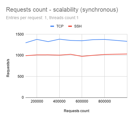
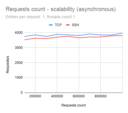
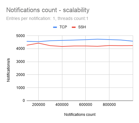
First, how well can OpenDaylight sustain performance (number of processed requests per second), while increasing the total amount of sent requests? Tests were executed in both variants, sending requests synchronously and also asynchronously.
In this scenario, it is desired, that the performance would be held around a constant value during all test cases.
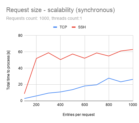
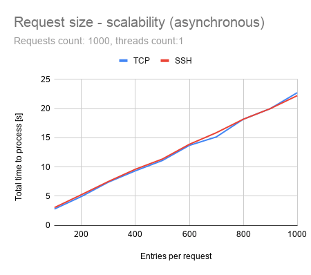
In the second case, we examined, how much time is needed to process all requests, affected by gradually increased request size (amount of elements sent within one request).
It is desired, that the total time needed to process all requests would be equal, or smaller, than the direct proportion of request size.
The purpose of this test is to measure, how many notifications, containing prefixes, can be received within one second.
All notifications were sent from a single NETCONF simulated device. No further processing of these notifications was done, except for counting received notifications, which was needed to calculate the performance results.
The model of these notifications is example-notifications@2015-06-11.yang. The time needed to process notifications is calculated as the time interval between receiving first the notification and receiving the last notification.
All notifications are sent asynchronously, while there are no responses for NETCONF notifications.
Prefixes/Notifications
Total Prefixes
TCP Performance
SSH Performance
1
100 000
4 365 notifications/s
4 365 prefixes/s
4 432 notifications/s
4 432 prefixes/s
2
200 000
3 777 notifications/s
7 554 prefixes/s
3 622 notifications/s
7 245 prefixes/s
10
1 000 000
1 516 notifications/s
15 167 prefixes/s
1 486 notifications/s
14 868 prefixes/s
Table 3 – Southbound performance test results
Southbound: Scalability Tests
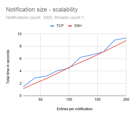
Scalability tests for the Southbound plugin were executed similarly to tests from the Northbound plugin – running both scenarios. Results are calculated by examining changes in performance, caused by an increasing amount of notifications and the total time needed, to process all notifications, while increasing the number of entries per notification.
In this test, the client tries to writevrf-routes (modeled by Cisco-IOS-XR-ip-static-cfg@2013-07-22.yang) to NETCONF enabled devices via the OpenDaylight controller.
It sends vrf-routes via RESTCONF to the controller, using the specific RPC ncmount:write-routes. The controller is responsible for storing these data into the simulated devices, via NETCONF.
Requests were sent two ways:
Synchronously: when each request was sent after receiving an answer for the previous request
Asynchronously: sending multiple requests as fast as possible, while maintaining the maximum number of 1000 concurrent pending requests, for which response has not yet been received.
Clients
Client type
prefixes/request
total prefixes
TCP performance
SSH performance
1
Sync
1
20 000
181 requests/s
181 routes/s
99 requests/s
99 routes/s
1
Async
1
20 000
583 requests/s
583 routes/s
653 requests/s
653 routes/s
1
Sync
10
200 000
127 requests/s
1 271 routes/s
89 requests/s
892 routes/s
1
Async
10
200 000
354 requests/s
3 546 routes/s
3 44 requests/s
3 444 routes/s
1
Sync
50
1 000 000
64 requests/s
3 222 routes/s
44 requests/s
2 209 routes/s
1
Async
50
1 000 000
136 requests/s
6 812 routes/s
138 requests/s
6 920 routes/s
16
Sync
1
20 000
1 318 requests/s
1 318 routes/s
424 requests/s
424 routes/s
16
Async
1
20 000
1 415 requests/s
1 415 routes/s
1 131 requests/s
1 131 routes/s
16
Sync
10
200 000
1 056 requests/s
10 564 routes/s
631 requests/s
6313 routes/s
16
Async
10
200 000
1 134 requests/s
11 340 routes/s
854 requests/s
8 540 routes/s
16
Sync
50
1 000 000
642 requests/s
32 132 routes/s
170 requests/s
8 519 routes/s
16
Async
50
1 000 000
639 requests/s
31 953 routes/s
510 requests/s
25 523 routes/s
32
Sync
1
320 000
2 197 requests/s
2 197 routes/s
921 requests/s
921 routes/s
32
Async
1
320 000
2 266 requests/s
2 266 routes/s
1 868 requests/s
1 868 routes/s
32
Sync
10
3 200 000
1 671 requests/s
16 713 routes/s
697 requests/s
6 974 routes/s
32
Async
10
3 200 000
1 769 requests/s
17 696 routes/s
1 384 requests/s
13 840 routes/s
32
Sync
50
16 000 000
797 requests/s
39 854 routes/s
356 requests/s
17 839 routes/s
32
Async
50
16 000 000
803 requests/s
40 179 routes/s
616 requests/s
30 809 routes/s
64
Sync
1
320 000
2 293 requests/s
2 293 routes/s
1 300 requests/s
1 300 routes/s
64
Async
1
320 000
2 280 requests/s
2 280 routes/s
1 825 requests/s
1 825 routes/s
64
Sync
10
3 200 000
1 698 requests/s
16 985 routes/s
1 063 requests/s
10 639 routes/s
64
Async
10
3 200 000
1 709 requests/s
17 092 routes/s
1 363 requests/s
13 631 routes/s
64
Sync
50
16 000 000
808 requests/s
40 444 routes/s
563 requests/s
28 172 routes/s
64
Async
50
16 000 000
809 requests/s
40 456 routes/s
616 requests/s
30 847 routes/s
Table 4 – E2E performance test results
E2E Scalability Tests
These tests were executed just like the previous scale test cases – by increasing the number of requests and request size.
Conclusion
The test results show good scalability of OpenDaylight in terms of keeping almost constant performance while processing larger requests and the ability to process a growing size of requests without decreasing final performance too much.
The only exceptions were cases when requests were sent synchronouslyusing SSH protocol. There is a sudden, significant increase in processing time when request size exceeds the value of 100. The maximum number of connected devices shows good results within the ability to connect more than 47 000 devices with 4GB of RAM and 26 000 devices with 2GB of RAM.
By using the TCP protocol, those numbers are even higher. TCP protocol, in comparison with SSH, results as the faster one, but at the cost of many advantages that the SSH protocol brings, like data encryption, which would be critical for companies, which needs to keep their data safe.
Examining differences in performance between SSH and TCP protocol is part of further investigation and more parts on Performance Testing in OpenDaylight, so stay tuned and subscribed!
We achieved a successful & effectiveintegration with the Firewall CNF and CDS, in an easy-to-understand use-case: block and allow traffic between two Docker containers.
Cloud-Native Firewall & CDS
With ONAP, orchestration management and automation of network services is simple, yet effective. It allows defining policies and act on network changes in real-time.
With CDS, users can configure other ONAP components as well – such as SDN-C or SDN-R, and thereby directly configure the network itself.
CDS is responsible for designing and controlling self-services – a fully self-defined software system. It makes these self-services so accessible, that minimal to no code development is required. It is usable also by non-programmers.
Position of CDS within the ONAP architecture
Self-contained services are defined by a Controller Blueprint Archive (CBA). The core of the CBA structure defines the service, according to TOSCA – the topology and orchestration specification for cloud applications. These blueprints are modeled, enriched to become fully self-contained TOSCA blueprints, and uploaded to CDS.
Our VPP-Agent-based Firewall CNF can be configured using CDS and afterward, effectively blocks or allows traffic between two Alpine Linux containers.
The workflow of applying a configuration to our Firewall CNF is comprised of two steps:
Resolve the configuration template
Apply the resolved configuration to the CNF, using the REST API
This shows the versatility and agility of our CNFs, by showcasing another possible integration in a popular project, such as ONAP.
The script in our demonstration provides a setup, where necessary containers are started and the data plane and control plane are brought in place.
The script will then showcase traffic (pinging) from the start point to endpoint in three scenarios:
Firewall CNF is not configured
Firewall CNF is configured by CDS to deny traffic
Firewall CNF is configured by CDS to allow traffic
PANTHEON.tech & ONAP
PANTHEON.tech is closely involved and following the development of various ONAP components.
The CPS component is of crucial importance in the ONAP project since it serves as a common data layer service, which preserves network-element runtime information, in form of database functionality.
PANTHEON.tech’s involvement in ONAP CPS includes creating an easy and common platform for testing deployments easier which highlights, where optimization is needed or achieved.
As part of our commitment to improve & develop ONAP functionality, PANTHEON.tech has introduced Performance Testing to the ONAP Configuration Persistence Service (CPS) component.
The test flow included the following operations:
Create a new anchor with a unique name in the given dataspace
Create data node – full data tree upload for a given anchor
Update data node – node fragment replacement
Remove anchor (and associated data)
This Performance Testing will make testing deployments easier and show, whether the optimization is needed or achieved.
You can download the first-ever, CPS Performance Testing report here:
CPS PDF Download
CPS Performance Test by PANTHEON.tech
Send download link to:
What is CPS in ONAP?
The Configuration Persistence Service component serves as a common data layer service, which preserves network-element runtime information, in form of database functionality. This runtime data, or information, needs to be persistent, so CPS provides a data repository for this data – this can include operational data.
CPS Performance Testing Environment
Businesses may rely on the ability to visualize and manage this data in their RAN network. So essentially, the goal of CPS is to improve the operation of data handling within ONAP – with better, efficient data layer services.
Use-cases for CPS are universal since the project is able to be utilized in Edge or core ONAP deployments, where a database is deployed with each installation. Proposed use-cases also include Edge-2-Edge Network Slicing. Not to mention the OPEX you will be saving on.
Our Commitment to Open-Source
Yes, we are the largest contributor to OpenDaylight. But we also contribute code to FD.io VPP or ONAP, amongst others. We see open-source as “a philosophy of freedom, meaningfulness, and the idea that wisdom should be shared”, as we mentioned in another post. And we will continue to work with the wonderful communities of projects we have close at heart.
What if I told you, that there is an out-of-the-box pre-packaged microservice-ready application you can easily use for managing network elements in your SDN use case? And that it is open-sourced and you can try it for free? Yep, you heard it right.
The application consists of lighty.io modules packed together within various technologies – ready to be used right away.
Do you have a more complex deployment, and are using Helm to deploy into Kubernetes? Or you just need to use Docker images? Or you want to handle everything by yourself and the only thing you need is a runnable application? We got you covered.
lighty.io RESTCONF-NETCONF Application
The most common use case we see at our customers is for an SDN controller to handle NETCONF devices via REST endpoints. This is due to ease of integration to e.g. OSS and BSS systems, or ITSM systems, as these already have REST API interfaces and adapters.
This is where our first lighty.io application comes in – the lighty.io RNC application, where RNC stands for RESTCONF-NETCONF-controller.
Use Cases: Facilitate & Translate Network Device Communication
Imagine a scenario, where the ONAP Controller Design Studio (CDS) component needs to communicate with both RESTCONF & NETCONF devices.
lighty.io RESTCONF-NETCONF Controller enables and facilitates communication to both RESTCONF/NETCONF devices while translating communication both ways!
Its usability and features can save you timeand resources in a variety of telco related scenarios:
At the heart of the application is the lighty.io controller. It provides core OpenDaylight services like MD-SAL, datastores, YANG Tools, handles global schema context, and more.
NETCONF southbound plugin serves as an adapter for NETCONF devices. It allows lighty.io to connect and communicate with them, execute RPCs, and read/write configuration.
RESTCONF northbound plugin is responsible for RESTCONF endpoints. These are used for communication between a user (or another application, like the aforementioned OSS/BSS systems, workflow managers, or ServiceNow for example) and the lighty.io application. RESTCONF gives us access to the so-called mount points serving as a proxy to devices.
These three mentioned components make up the core of the lighty.io RNC Application. Together, they form a base of the application. But of course, there is no such thing as one solution to rule them all.
Oftentimes, there is a need for side-car functionalities to the RNC, that is best built bespoke, that fulfill some custom business logic. Or enhance the RESTCONF API endpoints with side-load data.
We provide the means to customize and configure the lighty.io RNC application via configuration files to better fit your needs.
And if there is something we didn’t cover, do not hesitate to contact us or create a Pull Request or issue in our GitHub repository. We provide commercial custom development, developer, and operational support to enhance your efforts.
what is the base URL of the RC endpoints to RESTCONF endpoints
what is the name of the network topology where NETCONF is listening
which YANG models should be available in the lighty.io app itself
and more
But wait! There is more!
There are some special configurations too with a bit bigger impact
One of them is an option to enable HTTPS for RESTCONF endpoints. When useHttps is set to true, HTTPS will be enabled. It is possible to specify a custom key-store too and we recommend doing so. But just for some tests default keystore should be more than enough.
The option enableAAA is used to enable the lighty-aaa module. This module is responsible for authorization, authentication, and accounting which for example enables to use Basic Authentication for RESTCONF northbound interface.
Generally, it’s a good practice to consider SDN controllers like this one as a stateless service. Especially in a complex and dynamic deployment with a bigger amount of services.
But if you want to initialize configurational datastore with some data right after startup, it’s possible with the “initialConfigData“ part of the configuration. For example, you insert connection information about a NETCONF device, so the lighty.io application will connect to it right after it starts.
As mentioned in the beginning, we provide three main types of deployment: Helm chart for deployment in Kubernetes, Docker image, and a “zip” distribution containing all necessary jar files to run the application.
A step-by-step guide on how to build these artifacts from code can be found in a lighty.io RNC README.md file. It also contains steps on how to start and configure it.
Helm chart and Docker image can be also downloaded from public repositories.
Docker image can be downloaded from our GitHub Packages or via command:
In case you need an SDN controller for NETCONF devices providing RESTCONF endpoints, give lighty.io RNC a try. The guides linked above should be pretty straightforward.
And if you need any help, got some cool ideas, or want to use our solutions, you can contact us here!
PANTHEON.tech has made its data plane for managing cloud-native network functions, StoneWork, available on the GNS 3 marketplace. This makes it easy for anybody to try out our all-in-one solution, which can combine multiple cloud-native network functions from our CNF portfolio, in a separate environment.
This tutorial will give you the basics on how to set-up StoneWork in an environment, where you can safely test out interaction and its positioning within your (simulated) network.
The goal of this tutorial is to have a basic setup, where we will:
Import, or copy & paste a YAML configuration via the three-dot menu in the Configuration tab. We have conveniently placed an Examples folder, with a JSON Schema that serves as the
Errors will then be highlighted, against the imported JSON schema.
The JSON Schema specification recommends to use the definitions key, where all definitions should be located. Then, you should use a relative path to point to the definitions.
Our implementation of the JSON schema requires a definitions object, if the ref ID links to a definition and does not use a relative path.
Not supported: Loading definitions from external URIs
Feedback for CNF Tools
Leave us your feedback here or create an Issue in the repository of the CDNF.io YAML Editor. Explore our portfolio of cloud-native network functions, developed by PANTHEON.tech.
Here, StoneWork enables you to securely and remotely access your management plane.
StoneWork is a solution which, thanks to its modular architecture, enables you to combine multiple CNFs from the CNF portfolio, using only one data-plane, to increase the overall throughput, while keeping rich functionality.
One of the many features of StoneWork is IPSec, which we will talk about in this post.
StoneWork IPSec + SONiC
This case study briefly describes, how the StoneWork IPsec appliance can be used on your SONiC enabled switch to secure & tunnel your OOB management SONiC interface.
Stonework is part of our CNF portfolio. It is an enhanced VPP distribution, which serves as an all-in-one switch/router/firewall.
In this demonstration, two SONiC OS instances are provisioned to represent two IPSec gateways. But instead of actual physical switches, each SONiC OS runs inside a Docker container with a P4-simulated SAI behavioral model software switch ASIC underneath.
This P4 ASIC is also running as a separate container, to keep the emulated physical interfaces separated from kernel-space ports. A link between the ASIC and SONiC container is a network namespace reference /var/run/netns/sw_net that P4 ASIC expects to point to ASIC container from the filesystem of the SONiC container.
On top of that, there is a StrongSwan appliance running in a container, using the same network namespace as SONiC for the sake of AF_PACKET. In total there are three containers to represent one switch.
In-between the switches there is a “bridge” container, used only to capture traffic and verify that it is indeed encrypted. On the opposite side of switches, there are containers representing hosts – one is used as a TCP client, the other as a server.
What is SONiC?
SONiC is a Linux-based, network operating system, available as an open-source project, meant for network routers & switches.
The architecture is similar to that of OpenDaylight or lighty.io – it is composed of modules, on top of a centralized infrastructure, which is easily scalable.
Its main benefits are the usage of the Redis-engine infrastructure & placement of modules into Docker containers. The primary functional components are DHCP-Relay, PMon, SNMP, LLDP, BGP, TeamD, Database, SWSS, SyncD.
SONiC covers all the components needed for a complete L3 device. Its main use-case presents a cloud-data center, with the possibility of sharing software stacks among different platforms. Currently, over 100 platforms are officially supported.
An important concept of SONiC is that it does not interact with the hardware directly. Instead, its programs switch ASIC via the vendor-neutral Switch Abstraction Interface or SAI for short.
This approach, on one hand, allows maintaining vendor independence, while decoupling the network software and hardware. On the other hand, it creates boundaries on what can be performed with the underlying networking hardware.
Customers can create, validate and visualize the YANG data model of their application, without the need to call any other external tool – just by using the lighty.io framework.
YANG Tools helps to parse YANG modules, represent the YANG model in Java, and serialize/deserialize YANG model data. However, a custom YANG module can contain improper data that would result in an application failure. To avoid such annoying situations, PANTHEON.tech engineers created the lighty YANG Validator.
Its LightyController component utilizes OpenDaylight’s core components, including YANGtools, that provides a set of tools and libraries for YANG modeling of the network topology, configuration, and state data as defined by YANG 1.0 and YANG 1.1 models.
Prerequisites
Download the distribution from this page.
Make sure to run the tool in Linux and with Java installed.
Unzip the folder and read through the README.md file
What does the lighty YANG Validator offer?
The lighty YANG Validator (lighty-yang-validator) was inspired by pyang – python YANG validation tool. It checks the YANG module using the YANG Parser module. In case of any problem during parsing, the corresponding stack trace is returned to let you know what’s wrong and where.
In addition to the pyang implementation, the lighty YANG Validator, built on top of OpenDaylight’s YANG engine, checks not only the standard YANG compatibility but it validates the given module as a module compatible with lighty.io or OpenDaylight framework.
Users can choose to validate only one module or all modules within the given directory.
It’s not necessary to have all the imported and included modules of a validating module in the same path. It is possible to use -p, –path option with a path or colon-separated paths to needed module(s). YANG Validator can search for modules recursively within the file structure.
Of course, the customer can decide to search for the file just by module name instead of specifying the whole path!
Backwards Compatibility
The lighty YANG Validator allows checking the backward compatibility of the updated YANG module via –check-update-from option. Customers can select to validate backward compatibility according to RFC6020 or RFC7950.
The lighty YANG Validator can be further used for:
Verification of backward-compatibility for a module
Notification of users about module status change (removal/deprecation)
Simplify the YANG file
The YANG file is possible to simplify based on the XML payload. The resulting data model can be reduced by removing all nodes that are defined with an “if-feature”. This functionality is very useful with huge YANG files, that are tested with some basic configuration and not all schema nodes are used.
Utilization of such trimmed YANG files can significantly speed uploading of customer’s application in the development phase when the application is started repetitively. Thus, it saves overall development time. A simplified YANG file is printed out to standard output unless the output directory is defined.
User can choose between the following output types:
Tree in format \<status>–\<flags> \<name>\<opts> \<type> <if-features>
Name-Revision in format \<module_name>@\<revision>
List of all modules that validated module depends on
JSON Tree with all the node information
HTML Page with javascript for the visualization of the yang tree
YANG File / simplified YANG file
Goal: Create a stable and reliable custom application
lighty.io was developed to provide a lightweight implementation of core OpenDaylight components so customers are able to run their applications in a plain Java SE environment. PANTHEON.tech keeps working on the improvements for that framework to make its usage as easy as possible to the customers to create stable and reliable applications.
One step forward in this journey is the lighty YANG Validator – customers can create, validate and visualize the YANG data model of their application just by using the lighty.io framework without the need to call any other external tool.
A network can get messy. That is why many service providers require a Network Orchestrator, to fill the gap between managing hundreds of devices & corresponding services like SNMP, NETCONF, REST and others. This is where Cisco’s Network Services Orchestrator comes into play and translates service orders to various network devices in your network.
An NSO serves as a translator. It breaks up high-level service layers, from management & resource layers – connecting various network functions, which may run in a virtualized or hardware environment. It defines how these network functions interact with other infrastructures and technologies within the network.
We have introduced Ansible & AWX for automation in the past. Since we also enjoy innovation, we decided to create this guide on installing Cisco NSO, and it’s usage with lighty.io & ONAP (SDN-C).
The installation package can be downloaded from the official Cisco developer website. This guide contains steps on how to install the Cisco NSO. We will use the NSO 5.1.0.1 version in this tutorial. This tutorial was tested on Ubuntu 18.04 LTS.
Don’t forget to set NCS_DIR variable and source ncsrc file!
In the output, you should see connect-result and sync-result from all three devices.
To leave CLI, press CTRL+D.
Create Cisco NSO Service
Go to the packages directory and use ncs-make-package command:
cd packages
ncs-make-package --service-skeleton template acl-service --augment /ncs:services
This will create the directory acl-service with a structure containing templates and default YANG models. Templates are used for applying configurations to devices. With the YANG file, we can model how our service can be activated and what parameters it uses.
Now, open the template XML file acl-service/templates/acl-service-template.xml and replace its content with:
This template will be used for configuring selected devices. It will add access-group with specified interface_type, interface_number,ACL_Name and ACL_Direction variables to their configuration.
The values of the mentioned variables will be set when we will activate this service. These variables are modeled in the YANG file, which we are going to update now.
Replace the content of the acl-service/src/yang/acl-service.yang file with:
And now log into the Cisco NSO CLI and reload the packages:
ncs_cli -C -u admin
packages reload
The output should look similar to this:
admin@ncs# packages reload
>>> System upgrade is starting.
>>> Sessions in configure mode must exit to operational mode.
>>> No configuration changes can be performed until upgrade has completed.
>>> System upgrade has completed successfully.
reload-result {
package acl-service
result true
}
reload-result {
package cisco-ios-cli-3.0
result true
}
Now a Cisco NSO instance with three simulated devices should be up and running!
Turn off and clean Cisco NSO
Later when you will want to stop and clean what you started, call these commands in your project directory:
OpenDaylight‘s distribution package remained the same for several years. But what if there is a different way to do this, making distribution more aligned with the latest containerization trends? This is where an OpenDaylight Static Distribution comes to the rescue.
Original Distribution & Containerized Deployments
Let’s take a quick look at the usual way.
A standard distribution is made up of:
a pre-configured Apache Karaf
a full set of OpenDaylight’s bundles (modules)
It’s an excellent strategy for when the user wants to choose modules and build his application dynamically from construction blocks. Additionally, Karaf provides a set of tools that can affect configuration and features in runtime.
However, when it comes to micro-services and containerized deployments, this approach confronts some best practices for operating containers – statelessness and immutability.
Perks of a Static Distribution
Starting from version 4.2.x, Apache Karaf provides the capability to build a static distribution, aiming to be more compatible with the containerized environment – and OpenDaylight can use that as well.
So, what are the differences between a static vs. dynamic distribution?
Specified List of Features
Instead of adding everything to the distribution, you only need to specify a minimal list of features and required bundles in your runtime, so only they will be installed. This would help produce a lightweight distribution package and omit unnecessary stuff, including some Karaf features from the default distribution.
Pre-Configured Boot-Features
Boot features are pre-configured, no need to execute any feature installations from Karaf’s shell.
Configuration Admin
Configuration admin is replaced with a read-only version that only picks up configuration files from the ‘/etc/’ folder.
Speed
Bundle dependencies are resolved and verified during the build phase, which leads to more stable builds overall.
How to Build a Static Distribution with OpenDaylight’s Components
The latest version of the odl-parent component introduced a new project called karaf-dist-static, which defines a minimal list of features needed by all OpenDaylight’s components (static framework, security libraries, etc.).
This can be used as a parent POM to create our own static distribution. Let’s try to use it and assemble a static distribution with some particular features.
Assuming that you already have an empty pom.xml file, in the first step, we’re going to declare the karaf-dist-static project as a parent for our one:
Optionally, you can override two properties to disable the assembling of .zip/tar.gz archives with a distribution. Default values are ‘true’ for both properties.Let’s make an assumption, that we only need the ZIP:
This example aims to demonstrate how to produce a static distribution containing NETCONF southbound connectors and RESTCONF northbound implementation.Let’s add the corresponding items to the dependencies section:
Once we have these features on the dependency list, we can add them to Karaf’s Maven plugin configuration. Usually, when you want to add some OpenDaylight’s features, you can use the <bootFeatures> container.This should work fine for everything, except features delivered with a Karaf framework (like ssh,diagnostic, etc.).
When it comes to adding features provided by the Karaf framework, a <startupFeatures> block should be used; as we are going to check the installation of the features within the static distribution.
If you check the log messages, you probably will notice the KAR artifact is not the same one we had for dynamic distribution (in dynamic distribution, you can expect the following one – org.apache.karaf.features/framework/4.3.0/kar).
[INFO] Loading direct KAR and features XML dependencies
[INFO] Standard startup Karaf KAR found: mvn:org.apache.karaf.features/static/4.3.0/kar
[INFO] Feature static will be added as a startup feature
Eventually, we can check the output directory of the maven build – it should contain an ‘assembly’ folder with a static distribution we created and netconf-karaf-static-1.0.0-SNAPSHOT.zip archive that contains this distribution.
$ ls --group-directories-first -1 ./target
antrun
assembly
classes
dependency-maven-plugin-markers
site
checkstyle-cachefile
checkstyle-checker.xml
checkstyle-header.txt
checkstyle-result.xml
checkstyle-suppressions.xml
cpd.xml
netconf-karaf-static-1.0.0-SNAPSHOT.zip
While a ZIP archive can be used as an artifact, you would usually like to push to some repository; we will verify our distribution by running Karaf from the assembly folder.
./assembly/bin/karaf
If everything goes well, you should see some system messages saying that Karaf is started, following by a shell command-line interface:
Apache Karaf starting up. Press Enter to open the shell now...
100% [========================================================================]
Karaf started in 1s. Bundle stats: 50 active, 51 total
________ ________ .__ .__ .__ __
\_____ \ ______ ____ ____ \______ \ _____ ___.__.| | |__| ____ | |___/ |_
/ | \\____ \_/ __ \ / \ | | \\__ \< | || | | |/ ___\| | \ __\
/ | \ |_> > ___/| | \| ` \/ __ \\___ || |_| / /_/ > Y \ |
\_______ / __/ \___ >___| /_______ (____ / ____||____/__\___ /|___| /__|
\/|__| \/ \/ \/ \/\/ /_____/ \/
Hit '<tab>' for a list of available commands
and '[cmd] --help' for help on a specific command.
Hit '<ctrl-d>' or type 'system:shutdown' or 'logout' to shutdown OpenDaylight.
opendaylight-user@root>
With a static distribution, you don’t need to do any feature installation manually.
Let’s just check if our features are running by executing the following command
feature:list | grep 'Started'
The produced output will contain a list of already started features; among them, you should find features we selected in our previous steps.
...
odl-netconf-connector | 1.10.0.SNAPSHOT │ Started │ odl-netconf-1.10.0-SNAPSHOT │ OpenDaylight :: Netconf Connector
odl-restconf-nb-rfc8040 | 1.13.0.SNAPSHOT │ Started │ odl-restconf-nb-rfc8040-1.13.0-SNAPSHOT │ OpenDaylight :: Restconf :: NB :: RFC8040
...
We can also run an additional check by sending a request to the corresponding RESTCONF endpoint:
Now, we can produce immutable & lightweight OpenDaylight distributions with a selected number of pre-installed features, which can be the first step to create Docker images that would be fully compliant for the containerized deployment.
Our next steps would be to make logging and clustered configuration more suitable for running in containers, but that’s a topic for another article.
Binding Query (BQ) is an MD-SAL module, currently located at OpenDaylight version master (7.0.5), 6.0.x, and 5.0.x. Its primary function is to filter data from the Binding Awareness model.
To use BQ, it is required to create QueryExpression and QueryExecutor. QueryExecutor contains BindingCodecTree and data represented by the Binding Awareness model. A filter will be applied to this data and all operations from QueryExpression.
QueryExpression is created from the QueryFactory class. Creating a QueryFactory is started with the querySubtree method. Here, it is entered as an instance identifier, and it has to be at the root of data from QueryExecutor.
The next step will be to create a path to the data, which we want to filter – and then apply the required filter. When QueryExpression is ready, it will be applied with the method executeQuery in QueryExecutor. One QueryExpression can be used on multiple QueryExecutors with the same data schema.
Prerequisites for Binding Query
Now, we will demonstrate how to actually use Binding Query. We will create a YANG model for this purpose:
module queryTest {
yang-version 1.1;
namespace urn:yang.query;
prefix qt;
revision 2021-01-20 {
description
"Initial revision";
}
grouping container-root {
container container-root {
leaf root-leaf {
type string;
}
leaf-list root-leaf-list {
type string;
}
container container-nested {
leaf nested-leaf {
type uint32;
}
}
}
}
grouping list-root {
container list-root {
list top-list {
key "key-a key-b";
leaf key-a {
type string;
}
leaf key-b {
type string;
}
list nested-list {
key "identifier";
leaf identifier {
type string;
}
leaf weight {
type int16;
}
}
}
}
}
grouping choice {
choice choice {
case case-a {
container case-a-container {
leaf case-a-leaf {
type int32;
}
}
}
case case-b {
list case-b-container {
key "key-cb";
leaf key-cb {
type string;
}
}
}
}
}
container root {
uses container-root;
uses list-root;
uses choice;
}
}
Then, we will build and create a Binding Awareness model, with some test data from the provided YANG model.
public Root generateQueryData() {
HashMap<NestedListKey, NestedList> nestedMap = new HashMap<>() {{
put(new NestedListKey("NestedId"), new NestedListBuilder()
.setIdentifier("NestedId")
.setWeight((short) 10)
.build());
put(new NestedListKey("NestedId2"), new NestedListBuilder()
.setIdentifier("NestedId2")
.setWeight((short) 15)
.build());
}};
HashMap<NestedListKey, NestedList> nestedMap2 = new HashMap<>() {{
put(new NestedListKey("Nested2Id"), new NestedListBuilder()
.setIdentifier("Nested2Id")
.setWeight((short) 10)
.build());
}};
HashMap<TopListKey, TopList> topMap = new HashMap<>() {{
put(new TopListKey("keyA", "keyB"),
new TopListBuilder()
.setKeyA("keyA")
.setKeyB("keyB")
.setNestedList(nestedMap)
.build());
put(new TopListKey("keyA2", "keyB2"),
new TopListBuilder()
.setKeyA("keyA2")
.setKeyB("keyB2")
.setNestedList(nestedMap2)
.build());
}};
HashMap<CaseBContainerKey, CaseBContainer> caseBMap = new HashMap<>() {{
put(new CaseBContainerKey("test@test.com"),
new CaseBContainerBuilder()
.setKeyCb("test@test.com")
.build());
put(new CaseBContainerKey("test"),
new CaseBContainerBuilder()
.setKeyCb("test")
.build());
}};
RootBuilder rootBuilder = new RootBuilder();
rootBuilder.setContainerRoot(new ContainerRootBuilder()
.setRootLeaf("root leaf")
.setContainerNested(new ContainerNestedBuilder()
.setNestedLeaf(Uint32.valueOf(10))
.build())
.setRootLeafList(new ArrayList<>() {{
add("data1");
add("data2");
add("data3");
}})
.build());
rootBuilder.setListRoot(new ListRootBuilder().setTopList(topMap).build());
rootBuilder.setChoiceRoot(new CaseBBuilder()
.setCaseBContainer(caseBMap)
.build());
return rootBuilder.build();
}
For better orientation in the test-data structure, there is also a JSON representation of the data we will use:
From the Binding Awareness model queryTest shown above, we can create a QueryExecutor. In this example, we will use the SimpleQueryExecutor. As a builder parameter, we entered BindingCodecTree. Afterwards, this will be added into the Binding Awareness data by method, which we created above.
public QueryExecutor createExecutor() {
return SimpleQueryExecutor.builder(CODEC)
.add(generateQueryData())
.build();
}
Create a Query & Filter Data
Now, we can start with an example on how to create a query and filter some data. In the first example, we will describe how to filter the container by the value of his leaf. In the next steps, we will create a QueryExpression.
First, we will create a QueryFactory from the DefaultQueryFactory. The DefaultQueryFactory constructor takes BindingCodecTree as a parameter.
QueryFactory factory = new DefaultQueryFactory(CODEC);
The next step is to create the DescendantQueryBuilder from QueryFactory. The querySubtree method takes the instance identifier as a parameter. This identifier should be a root node from our model. In this case, it is a container with the name root.
The last step is to define which values should be filtered and then build the QueryExpression. For this case, we will filter a specific leaf, with the value “root leaf”.
Now, the QueryExpression can be used to filter data from QueryExecutor. For creating QueryExecutor, we use the method defined above in “test query data”.
The next example will show how to use Binding Query to filter data from nested-list. This example will filter nested-list items, where the weight parameter equals 10.
In case that we wanted to get top-list elements, but only those which contain nested-leaf items with a weight greater than, or equals to, 15. It is possible to set a match on top-list containers and then continue with a condition to nested-list. With number operations, we can execute greaterThanOrEqual, lessThanOrEqual, greaterThan, and lessThan methods.
The last example shows how to filter choice data and matching their values in key-cb leaf. Conditions that are required to meet are defined in the pattern, which matches the email address.
Binding Query can be used to filter important data, as is shown in previous examples. With Binding Query, it is possible to filter data with various options and get all the required information. Binding Query can also support matching string by patterns and simple filter operations with numbers.
To provide the best experiences, we use technologies like cookies to store and/or access device information. Consenting to these technologies will allow us to process data such as browsing behavior or unique IDs on this site. Not consenting or withdrawing consent, may adversely affect certain features and functions.
Functional
Always active
The technical storage or access is strictly necessary for the legitimate purpose of enabling the use of a specific service explicitly requested by the subscriber or user, or for the sole purpose of carrying out the transmission of a communication over an electronic communications network.
Preferences
The technical storage or access is necessary for the legitimate purpose of storing preferences that are not requested by the subscriber or user.
Statistics
The technical storage or access that is used exclusively for statistical purposes.The technical storage or access that is used exclusively for anonymous statistical purposes. Without a subpoena, voluntary compliance on the part of your Internet Service Provider, or additional records from a third party, information stored or retrieved for this purpose alone cannot usually be used to identify you.
Marketing
The technical storage or access is required to create user profiles to send advertising, or to track the user on a website or across several websites for similar marketing purposes.